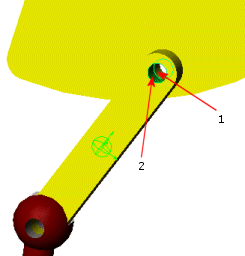
For this lesson, you are interested only in the loads transferred to the Link part during the motion analysis.
For the proper transfer of motion loads, you specify load-bearing faces for mates Concentric2 and Concentric3 of the Link part.
-
To specify load-bearing faces for Concentric2, in the FeatureManager design tree, under link<1>, right-click Concentric2 and select Edit Feature
 .
.
-
Click the Analysis tab
 .
.
-
Select Load Bearing Faces.
-
For Load bearing Faces/Edges
 , select Face 1 from the Plate part and Face 2 from the Link part.
For easier face selection, use the option Isolate components to hide the parts that are not associated with the mate.

-
Click
 twice.
-
To specify load-bearing faces for Concentric3:
- Repeat steps 1 to 3.
- For Load bearing Faces/Edges
 , select Face 1 from the Link component and Face 2 or Face 3 from the Punch component.
- Click
 twice.
Now you are ready to run the motion study.