The Configurator Table maps configurations of the screws and washers to each configuration of the bearing. The software populates the table, but you can edit the table to use other configurations. The table also provides columns where you specify the allowable range of diameters for auto-sizing.
-
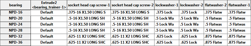
In the PropertyManager, click Configurator Table.
The following table appears. The columns in your table might be in a
different order, based on the order in which you selected components.
-
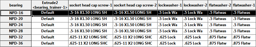
Change the configurations of the screws and washers specified for the
bearing configuration NPD-16.
Click the cell for each screw and washer and select the configuration that
matches the values highlighted in the table below.
-
Specify the allowable range of diameters for auto-sizing by entering the
values for the minimum and maximum diameters.
-
Click OK, then click
 .
.
-
Click
Save to This PC
 (Standard
toolbar). In the Save Modified Documents dialog box,
click Save
All.
(Standard
toolbar). In the Save Modified Documents dialog box,
click Save
All.
All the defining data for the Smart Component is saved in the
component document
bearing.SLDPRT:
- External references to the files of associated components
- Information to create associated features
- Information to reconstruct the training assembly
-
Close the training assembly.