Dimensions Overview
Dimensions in a SolidWorks drawing are associated with the model, and
changes in the model are reflected in the drawing.
Model Dimensions. Typically,
you create dimensions as you create each part feature, then insert those
dimensions into the various drawing views. Changing a dimension in the
model updates the drawing, and changing an inserted dimension in a drawing
changes the model.
Mark for Drawings. When creating
dimensions, you can specify whether the dimension should be included when
inserting model dimensions into drawings. Right-click the dimension and
select Mark For Drawing. You can
also specify that dimensions marked for drawings be inserted automatically
into new drawing views. Select Dimensions
marked for drawing under Auto
insert on view creation in Document
Properties - Detailing.
Reference Dimensions. You can
also add dimensions in the drawing document, but these are reference
dimensions, and are driven; you cannot edit the value of reference dimensions
to change the model. However, the values of reference dimensions change
when the model dimensions change.
Standard
Dimensions. You can create standard dimensions in drawings, such
as dimensions created in a sketch. This includes Smart, Horizontal, and Vertical
dimensions.
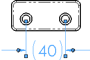
Rapid Dimension. Use rapid dimensioning
to place evenly spaced dimensions.
Color. By default, model dimensions
are black. This includes dimensions that are blue in the part or assembly
document (such as the extrusion depth). Reference dimensions are gray
and appear with parentheses by default. You can specify colors for various
types of dimensions in Tools,
Options, System
Options, Colors
and specify Add parentheses by default
in Document
Properties - Dimensions.
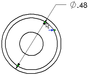
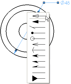
Arrows. Circular handles appear
on dimension arrows when dimensions are selected. When you click on an
arrowhead handle (on either handle if there are two for the dimension),
the arrows flip outside or inside. When you right-click on a handle, a
list of arrowhead styles appears. You can change the style of any dimension
arrowhead individually by this method.
|
|
|
|
Flipping the arrows |
Changing the arrowhead style |
Selection.
You can select dimensions by clicking anywhere on the dimension, including
dimension and extension lines and arrows.
Hide
and Show Dimensions. You can hide and show dimensions with Hide/Show
Annotations
 on the Annotation toolbar or View
menu. You can also right-click a dimension and select Hide
to hide the dimension. You can also hide and show dimensions in annotation
views. To show dimension names, click View
> Dimension Names or Hide/Show Items
  > View Dimension
Names
  (Heads-Up View toolbar).
Formatting.
The dimension
palette appears when you insert or select a dimension so you can easily
change the dimension's properties and formatting. You can change the tolerance,
precision, style, text, and other formatting options in the palette without
going to the PropertyManager.
Hide
and Show Lines. To hide a dimension line or extension
line, right-click the line and select Hide
Dimension Line or Hide Extension
Line. To show hidden lines, right-click the dimension or a visible
line and select Show Dimension Lines
or Show Extension Lines.
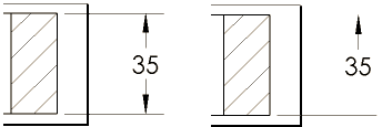
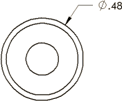
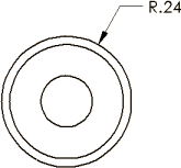
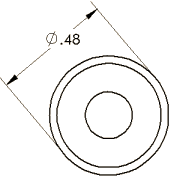
Radius
and Diameter Displays. You can change a dimension to diameter,
radius, or linear display. On screen, right-click a radius or diameter
dimension and select:
|
|
|
|
|
Display As Diameter.
This example is shown without the second arrow. Click Use
document second arrow to display both arrows. |
Display As Radius |
Display As Linear.
Sets the dimension to linear style (for diameter dimensions only.) |
 You can right-click and select the above options
only when you first create the dimension. If you edit the dimension later
on, right-click the dimension and select Display
Options, then select an option above.
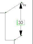
Slant. When you insert or select dimensions, handles
appear so you can drag the dimension to slant
the extension lines.
Display Options. Right-click
a dimension and select Display Options.
The choices available depend on the type of dimension and other factors
and can include the following:
Remove Slant
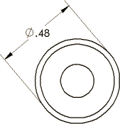
Center Dimension. When you drag dimension text between the
extension lines, the dimension text snaps between the center of the extension
lines.
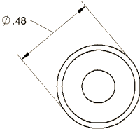
Offset Text.
Offsets dimension text from the dimension
line using a leader.
Change Plane
Align Ordinate
Jog
Re-Jog Ordinate
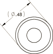
Show Parentheses. You can display driven (reference)
dimensions with or without parentheses. They are displayed with parentheses
by default.
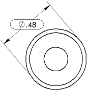
Show as Inspection
Display
As Diameter
Display
As Radius
Display
As Linear
Link external dim text. If you
insert text into a dimension in a drawing, this option inserts the text
into the dimension in the part or assembly as well. Right-click the top-level
icon in the drawing's FeatureManager design tree and select Link
external dim text to allow dimension text to propagate back to
the part or assembly.
 When linking text between an assembly and
a drawing, the dimension in the drawing must have been inserted with the
Model
Items tool.
Related Topics
Baseline
dimensions
Ordinate
dimensions
Modifying
dimensions
Moving
and copying dimensions
Dimension
Value PropertyManager
Creating
jogs in dimension extension lines
Adding
multiple jogs to radius, diameter, chamfer, or hole callout dimensions