Face Curves
You can extract iso-parametric (UV) curves from a face or surface. Applications
of this functionality include extracting the curves for imported surfaces
and then performing localized cleanup using the face curves.
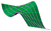
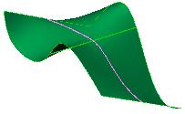
You can specify a mesh of evenly spaced curves or a position that creates
two orthogonal curves.
|
 |
 |
|
Mesh |
Position |
Each curve created by this process becomes a separate 3D sketch. However,
if you are editing a 3D sketch when you invoke the Face
Curves tool, all extracted curves are added to the active 3D sketch.
To extract iso-parametric curves:
-
Click Face Curves  (Sketch toolbar) or Tools,
Sketch Tools, Face Curves, then select a face or surface.
- or -
Select a face or surface, then click Face
Curves  or Tools,
Sketch Tools, Face Curves.
A preview of the curves appears
on the face. The curves are one color in one direction and another color
in the other direction. The colors correspond to the colors in the Face Curves
PropertyManager. The name of the face appears in the Face  box.
box.
Under Selections,
choose either:
 You cannot drag the vertex.
Under Options,
select or clear:
Constrain
to model. When selected, the curves are updated if the model changes.
Ignore holes.
Use for imported surfaces with internal gaps or loops. When selected,
the curves are generated across holes as though the surface were intact.
When cleared, the curves stop at the edges of holes.
-
Click OK  .
.
The curves appear as 3D sketches  in the FeatureManager
design tree.
 If surface edge information cannot be
matched, edge curves cannot be generated. The error message states: "Failed
to create X out of X face curves. Please consider using convert entities."
You can generate the missing curves by opening a 3D sketch and using the
Convert Entities
  sketch tool.