DimXpert Location Dimension
Use the Location Dimension tool  to apply linear and angular dimensions between two
DimXpert features
(excluding surface, fillet, chamfer, and pocket features). In the following procedure, you dimension the distance between two simple holes.
To use the DimXpert Location Dimension tool:
-
Click Location Dimension  (DimXpert toolbar) or Tools, DimXpert, Location Dimension.
-
Select the face of the origin feature.
 Edge selection is supported only when making a dimension between two planes. See the procedure below.
The Feature Selector appears in the graphics area with Hole selected. If necessary, select a different type of feature in the feature selector.
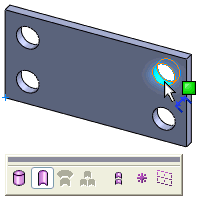
-
Click the face of the tolerance feature.
The feature selector remains displayed with a default feature type selected for the tolerance feature. If necessary, select a different type of feature in the feature selector. The location dimension is ready to be placed.
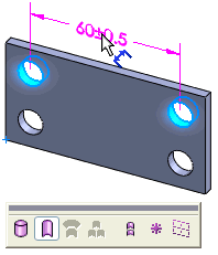
-
Click to place the dimension.
The
DimXpert PropertyManager
appears. The selected hole features are listed as Origin Feature  and Tolerance Feature
  under Reference Features.
|

|
-
If necessary, click Swap Features  to reverse the features. to reverse the features.
-
In general, you can attach dimensions to any edge of the feature. Select the dimension and use its drag handle to reposition the dimension.
|
-
Set the remaining PropertyManager options and click  .
.
The DimXpertManager updates to include the feature and dimension type.
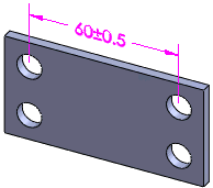
Using edge selection to place a location dimension between two planes:
-
Click Location Dimension  (DimXpert toolbar) or Tools, DimXpert, Location Dimension.
-
Select a linear edge bounded by two parallel faces that are perpendicular to the edge.
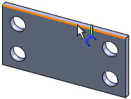
-
Click to place the dimension.
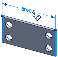
-
Set the PropertyManager options, then click  .
.
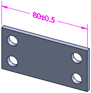
Notes
Dimensions:
Linear dimensions are applied between:
-
A combination of two parallel plane, axis, or line-type features
-
Two points
-
A point and a plane, axis, or line-type feature
-
Pairs of axes and lines that are skew (non-intersecting and non-parallel):
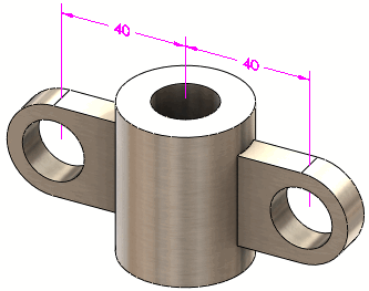
Angular dimensions are applied between a combination of two non-parallel plane, axis, or line-type features.
You can apply linear or angular dimensions to these features:
-
Point features: Intersect point and sphere
-
Plane features: Plane, notch, width, and intersect plane
-
Axis and Line features: Cone, cylinder, boss, simple hole, counterbore hole, countersink hole, slot, and intersect line
-
Point: Intersect point
Tolerance / Precision: Set the default tolerance and precision for location dimension at Tools, Options, Document Properties, DimXpert, Location Dimension.