|
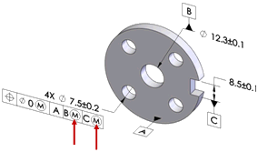
Apply MMC to datum features of size. Defines whether an MMC symbol is placed in the datum fields when the datum feature is a feature of size.
|
|
|
|
|
|
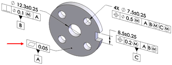
Use as primary datums: form gtol. Sets the tolerance value for the form tolerances that are applied to primary datum features. DimXpert uses this option when the primary datum feature is a plane, in which case a flatness tolerance is applied.
The dimension scheme shown was created with the Auto Dimension Scheme tool using datum A as the primary datum. Note the flatness tolerance applied to datum A.
|
|
|
|
|
|
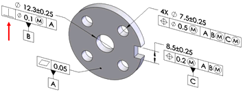
Use as secondary datums: orientation or location gtol. Sets the tolerance value for the orientation and location tolerances that are applied to secondary datum features.
The dimension scheme shown was created with the Auto Dimension Scheme tool using datum A as primary, and datum B as the secondary datum. Note the perpendicularity tolerance applied to datum B relative to datum A.
|
|
|
|
|
|
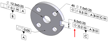
Use as tertiary datums: orientation or location gtol. Sets the tolerance value for the orientation and location tolerances that are applied to tertiary datum features.
The dimension scheme shown was created with the Auto Dimension Scheme tool using datum A as primary, datum B as secondary, and datum
C
as the tertiary datum feature. Note the position tolerance applied to datum
C
relative to datum A and B.
|
|
Basic dimensions
Use the basic dimensions option to enable or disable the creation of basic dimensions, and to select whether to use Chain or Baseline dimension schemes. This option applies to position tolerances created by the Auto Dimension Scheme, Geometric Tolerance, and Recreate basic dim commands.
|
|
Basic dimensions can be automatically created for the most common cases when applying geometric position tolerances to counterbore, countersink, cylinder, notch, simple hole, and slot features.
Shown are common examples of basic dimensions applied as Chain and Baseline dimensions.
|
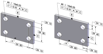
Chain Baseline
|
|
|
|
|
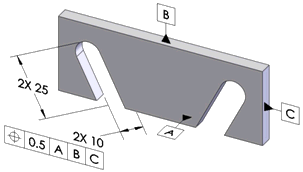
Basic dimensions are only created when they can be placed perpendicular to the feature's axis or plane. In the example shown, basic dimensions are not created because the notches are not parallel to one another or to any of the datum planes.
|
|
|
|
|
|
Use the Recreate basic dimensions command to create or repair the basic dimension scheme for a given geometric position tolerance.
For example, if you modify a hole pattern by adding or removing holes, the basic dimension scheme might not update as required. Run this command to repair it. When you run the command, DimXpert applies the dimension scheme, Baseline or Chain, that you set under Tools, Options, Document Properties, DimXpert, Geometric Tolerance, Basic dimensions.

|
|
|
|
|
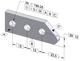
Chain. Creates chain dimensions between parallel pattern features. When the features are not parallel, baseline dimensions are used.
Chain dimensioning applied to a hole pattern
|
|
|
|
|
|
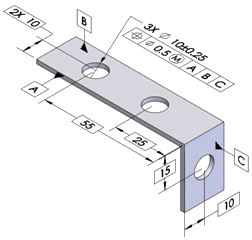
Baseline. Creates baseline dimensions that can be applied to any pattern regardless of their orientation to one another. In the example, the features within the pattern are not all parallel.
|
|
Position
Defines the tolerance values and criteria to use when creating position tolerances.
|
|
At MMC. Places an MMC (maximum material condition) symbol in the Tolerance 1 compartment of the feature control frame, when applicable.
|

|
|
|
|
|
Composite. Creates composite position tolerances.
|

|
|
|
|
|
Clear Composite to create single segmented position tolerances.
|

|
|
|
|
Surface profile
Defines the tolerance values and criteria to use when creating surface profile tolerances.
Composite. Creates composite profile tolerances.
|

|
|
|
|
|
Clear Composite to create single segmented profile tolerances.
|

|
|
|
|
Runout
Defines the tolerance to use when creating runout tolerances. Runout tolerances are created only when the Auto Dimension Scheme Part type is Turned and the Tolerance type is Geometric.
|