Expand IntroductionIntroduction
Expand AdministrationAdministration
Expand User InterfaceUser Interface
Collapse SolidWorks FundamentalsSolidWorks Fundamentals
Basic Concepts
Basic Commands: Cut, Copy, Paste, Undo, and Redo
Expand Help, Search, and Web ResourcesHelp, Search, and Web Resources
Expand Document BasicsDocument Basics
Collapse SolidWorks OptionsSolidWorks Options
Accessing the Options Dialog Box
Expand System OptionsSystem Options
Collapse Document PropertiesDocument Properties
Document Properties - Drafting Standard
Expand Document Properties - AnnotationsDocument Properties - Annotations
Expand Document Properties - DimensionsDocument Properties - Dimensions
Document Properties - Centerlines/Center Marks
DimXpert Options - Drawings
Document Properties - Virtual Sharp Display
Expand Document Properties - TablesDocument Properties - Tables
Expand Document Properties - View LabelsDocument Properties - View Labels
Document Properties - Detailing
Document Properties - Grid/Snap
Document Properties - Units
Document Properties - Line Font
Document Properties - Line Style
Document Properties - Line Thickness
Document Properties - Model Display
Document Properties - Material Properties
Document Properties - Image Quality
Document Properties - Sheet Metal
Document Properties - Plane Display
Expand Document Properties - DimXpertDocument Properties - DimXpert
Expand DisplayDisplay
Expand SelectionSelection
Expand File PropertiesFile Properties
Expand Measure ToolMeasure Tool
Expand SensorsSensors
Expand EquationsEquations
Expand Industry-Specific Design ToolsIndustry-Specific Design Tools
Xperts Overview
Add-Ins
SolidWorks Fast Start
Expand Object Linking and EmbeddingObject Linking and Embedding
Expand Recording and Playing MacrosRecording and Playing Macros
Expand Previous Release InteroperabilityPrevious Release Interoperability
SolidWorks API
SolidWorks Task Scheduler
Expand Moving from 2D to 3DMoving from 2D to 3D
Expand AssembliesAssemblies
Expand CircuitWorksCircuitWorks
Expand ConfigurationsConfigurations
Expand SolidWorks CostingSolidWorks Costing
Expand Design CheckerDesign Checker
Expand Design Studies in SolidWorksDesign Studies in SolidWorks
Expand Detailing and DrawingsDetailing and Drawings
Expand DFMXpressDFMXpress
Expand DriveWorksXpressDriveWorksXpress
Expand FloXpressFloXpress
Expand Import and ExportImport and Export
Expand Model DisplayModel Display
Expand Mold DesignMold Design
Expand Motion StudiesMotion Studies
Expand Parts and FeaturesParts and Features
Expand RoutingRouting
Expand Sheet MetalSheet Metal
Expand SimulationSimulation
Expand SimulationXpressSimulationXpress
Expand SketchingSketching
Expand Sustainability ProductsSustainability Products
Expand SolidWorks UtilitiesSolidWorks Utilities
Expand TolerancingTolerancing
Expand TolAnalystTolAnalyst
Expand ToolboxToolbox
Expand WeldmentsWeldments
Expand Workgroup PDMWorkgroup PDM
Expand TroubleshootingTroubleshooting
Glossary
Hide Table of Contents

Document Properties - Detailing

You can specify document-level drafting settings for detailing options. Available for all document types.

To open this page, with a drawing open, click Options (Standard toolbar), select the Document Properties tab, and then select Detailing .

Options

Display filter Select annotation types to display by default or select Display all types.
Text scale For part and assembly documents, clear Always display text at the same size to select a scale for the default size of annotation text.
Always display text at the same size Select to display all annotations and dimensions at the same size, regardless of zoom.
This option is disabled for drawings, which always zoom the text height.
Display items only in the view orientation in which they are created (Parts and assemblies only) Select to display annotations only when the model has the same orientation as when the annotation was added. Rotating the part or selecting a different view orientation removes the annotation from the display.
Display annotations / Display assembly annotations Select to display all annotation types that are selected in the Display filter. For assemblies, this option applies to the annotations that belong to the assembly and to the annotations that are displayed in the individual part documents.
Use assembly setting for all components Select to match the display settings for all annotations to the settings for the assembly document, regardless of the settings for individual part documents. Select Display assembly annotations in addition to this option to display different combinations of annotations.
Hide dangling dimensions and annotations For parts or assemblies, select to hide:
  • Dangling dimensions and annotations in referenced drawings that result from deleted features
  • Dangling reference dimensions that result from suppressed features
For drawings, select to hide dangling annotations.
Use model color for HLR/HLV in drawings Select to view the model colors of a part or assembly in a drawing in HLR/HLV. This setting overrides colors in Tools > Options > System Options > Colors. However, any assigned layer overrides this setting.

Link child view to parent view configuration Select to link child views, for example, a projected view, to the parent view configuration. If linked, changing the parent view configuration changes the child view.
Import annotations Clear From entire assembly to import only top-level assembly annotations.

Select to import annotations for all components, which might impact performance.

Auto insert on view creation Select:
  • Center marks - holes -part
  • Center marks - fillets -part
  • Center marks - slots -part
  • Dowel symbols -part

  • Center marks - holes -assembly
  • Center marks - fillets -assembly
  • Center marks - slots -assembly
  • Dowel symbols -assembly
  • Centerlines to add centerlines to model faces with parallel edges.
    Centerlines are not inserted automatically if the model is in Large Assembly Mode, or if the number of components exceeds the threshold for large assemblies, even if this option is selected.
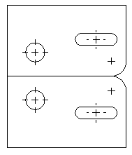
  • Balloons to add balloons to all visible components, without duplicates in multiple views
  • Dimensions marked for drawing to add dimensions to models, without duplicates in multiple views
    The dimensions are indicated in the part sketches as Mark for drawing.
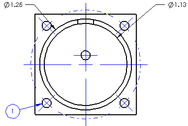
Cosmetic thread display Select High Quality to determine if cosmetic threads should be visible or hidden. For example, if a hole (not a through hole) is on the back of a model, and the model is in a front view, the cosmetic thread is hidden. You can set the display for each drawing view individually in the Drawing View PropertyManager under Cosmetic Thread Display.
Area hatch display Select Show halo around annotations to display space around dimensions and annotations that belong to the drawing view or a sketch and are on top of an area hatch.
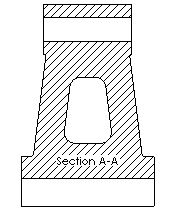
Selected

Cleared

View break lines Enter:
  • Gap to set the distance between break lines in a broken view
  • Extension to set length of the break lines beyond the model geometry in a broken view
Center of mass

Enter Symbol size to set a default symbol size.

Select Scale by view scale to automatically scale the center of mass symbol to the drawing view scale.


Provide feedback on this topic

SOLIDWORKS welcomes your feedback concerning the presentation, accuracy, and thoroughness of the documentation. Use the form below to send your comments and suggestions about this topic directly to our documentation team. The documentation team cannot answer technical support questions. Click here for information about technical support.

* Required

 
*Email:  
Subject:   Feedback on Help Topics
Page:   Document Properties - Detailing
*Comment:  
*   I acknowledge I have read and I hereby accept the privacy policy under which my Personal Data will be used by Dassault Systèmes

Print Topic

Select the scope of content to print:


x

We have detected you are using a browser version older than Internet Explorer 7. For optimized display, we suggest upgrading your browser to Internet Explorer 7 or newer.

 Never show this message again
x

Web Help Content Version: SOLIDWORKS 2013 SP05

To disable Web help from within SOLIDWORKS and use local help instead, click Help > Use SOLIDWORKS Web Help.

To report problems encountered with the Web help interface and search, contact your local support representative. To provide feedback on individual help topics, use the “Feedback on this topic” link on the individual topic page.