Expand IntroductionIntroduction
Expand AdministrationAdministration
Expand User InterfaceUser Interface
Collapse SolidWorks FundamentalsSolidWorks Fundamentals
Basic Concepts
Basic Commands: Cut, Copy, Paste, Undo, and Redo
Expand Help, Search, and Web ResourcesHelp, Search, and Web Resources
Expand Document BasicsDocument Basics
Collapse SolidWorks OptionsSolidWorks Options
Accessing the Options Dialog Box
Expand System OptionsSystem Options
Collapse Document PropertiesDocument Properties
Document Properties - Drafting Standard
Expand Document Properties - AnnotationsDocument Properties - Annotations
Expand Document Properties - DimensionsDocument Properties - Dimensions
Document Properties - Centerlines/Center Marks
DimXpert Options - Drawings
Document Properties - Virtual Sharp Display
Expand Document Properties - TablesDocument Properties - Tables
Expand Document Properties - ViewsDocument Properties - Views
Document Properties - Detailing
Document Properties - Grid/Snap
Document Properties - Units
Document Properties - Line Font
Document Properties - Line Style
Document Properties - Line Thickness
Document Properties - Model Display
Document Properties - Material Properties
Document Properties - Image Quality
Document Properties - Sheet Metal
Document Properties - Plane Display
Collapse Document Properties - DimXpertDocument Properties - DimXpert
DimXpert Size Dimension Options
DimXpert Location Dimension Options
DimXpert Chain Dimension Options
DimXpert Geometric Tolerance Options
DimXpert Chamfer Controls Options
DimXpert Display Options
Expand DisplayDisplay
Expand SelectionSelection
Expand File PropertiesFile Properties
Expand Measure ToolMeasure Tool
Expand SensorsSensors
Expand EquationsEquations
Expand Industry-Specific Design ToolsIndustry-Specific Design Tools
Xperts Overview
Add-Ins
SolidWorks Fast Start
Expand Object Linking and EmbeddingObject Linking and Embedding
Expand Recording and Playing MacrosRecording and Playing Macros
Expand  Future Version Components in Earlier Releases Future Version Components in Earlier Releases
SolidWorks API
SolidWorks Task Scheduler
Expand Moving from 2D to 3DMoving from 2D to 3D
Expand AssembliesAssemblies
Expand CircuitWorksCircuitWorks
Expand ConfigurationsConfigurations
Expand SolidWorks CostingSolidWorks Costing
Expand Design CheckerDesign Checker
Expand Design Studies in SolidWorksDesign Studies in SolidWorks
Expand Detailing and DrawingsDetailing and Drawings
Expand DFMXpressDFMXpress
Expand DriveWorksXpressDriveWorksXpress
Expand FloXpressFloXpress
Expand Import and ExportImport and Export
Expand Model DisplayModel Display
Expand Mold DesignMold Design
Expand Motion StudiesMotion Studies
Expand Parts and FeaturesParts and Features
Expand RoutingRouting
Expand Sheet MetalSheet Metal
Expand SimulationSimulation
Expand SimulationXpressSimulationXpress
Expand SketchingSketching
Expand Sustainability ProductsSustainability Products
Expand SolidWorks UtilitiesSolidWorks Utilities
Expand TolerancingTolerancing
Expand TolAnalystTolAnalyst
Expand ToolboxToolbox
Expand WeldmentsWeldments
Expand Workgroup PDMWorkgroup PDM
Expand TroubleshootingTroubleshooting
Glossary
Hide Table of Contents

DimXpert Geometric Tolerance Options

These options set the tolerance values and criteria for generating geometric tolerance schemes created by the Auto Dimension Scheme tool.
These options apply to geometric tolerances you apply using DimXpert for parts only. They do not affect pre-existing features, dimensions, or tolerances.
Apply MMC to datum features of size Defines whether an MMC symbol is placed in the datum fields when the datum feature is a feature of size.
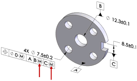
Use as primary datums: form gtol. Sets the tolerance value for the form tolerances that are applied to primary datum features. DimXpert uses this option when the primary datum feature is a plane, in which case a flatness tolerance is applied.
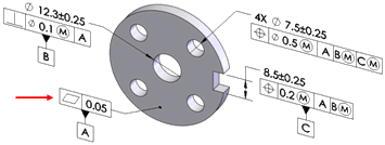


The dimension scheme shown was created with the Auto Dimension Scheme tool using datum A as the primary datum. Note the flatness tolerance applied to datum A.

Use as secondary datums: orientation or location gtol Sets the tolerance value for the orientation and location tolerances that are applied to secondary datum features.
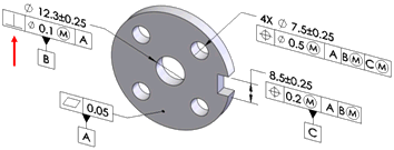


The dimension scheme shown was created with the Auto Dimension Scheme tool using datum A as primary, and datum B as the secondary datum. Note the perpendicularity tolerance applied to datum B relative to datum A.

Use as tertiary datums: orientation or location gtol Sets the tolerance value for the orientation and location tolerances that are applied to tertiary datum features.
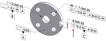
The dimension scheme shown was created with the Auto Dimension Scheme tool using datum A as primary, datum B as secondary, and datum C as the tertiary datum feature. Note the position tolerance applied to datum C relative to datum A and B.

Basic dimensions Use the basic dimensions option to enable or disable the creation of basic dimensions, and to select whether to use Chain or Baseline dimension schemes. This option applies to position tolerances created by the Auto Dimension Scheme, Geometric Tolerance, and Recreate basic dim commands.

Basic dimensions can be automatically created for the most common cases when applying geometric position tolerances to counterbore, countersink, cylinder, notch, simple hole, and slot features.

Chain

Creates chain dimensions between parallel pattern features. When the features are not parallel, baseline dimensions are used.

Baseline

Creates baseline dimensions that can be applied to any pattern regardless of their orientation to one another. In the example, the features within the pattern are not all parallel.

Basic dimensions are only created when they can be placed perpendicular to the feature's axis or plane. In the example shown, basic dimensions are not created because the notches are not parallel to one another or to any of the datum planes.
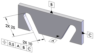
Use the Recreate basic dimensions command to create or repair the basic dimension scheme for a given geometric position tolerance.

For example, if you modify a hole pattern by adding or removing holes, the basic dimension scheme might not update as required. Run this command to repair it. When you run the command, DimXpert applies the dimension scheme, Baseline or Chain, that you set under Tools > Options > Document Properties > DimXpert > Geometric Tolerance .

Chain dimensioning applied to a hole pattern
Baseline
Position Defines the tolerance values and criteria to use when creating position tolerances.

At MMC

Places an MMC (maximum material condition) symbol in the Tolerance 1 compartment of the feature control frame, when applicable.

Composite

Creates composite position tolerances.

Clear Composite to create single segmented position tolerances.

Surface profile Defines the tolerance values and criteria to use when creating surface profile tolerances.

Composite

Creates composite profile tolerances.

Clear Composite to create single segmented profile tolerances.

Runout Defines the tolerance to use when creating runout tolerances. Runout tolerances are created only when the Auto Dimension Scheme Part type is Turned and the Tolerance type is Geometric.


Provide feedback on this topic

SOLIDWORKS welcomes your feedback concerning the presentation, accuracy, and thoroughness of the documentation. Use the form below to send your comments and suggestions about this topic directly to our documentation team. The documentation team cannot answer technical support questions. Click here for information about technical support.

* Required

 
*Email:  
Subject:   Feedback on Help Topics
Page:   DimXpert Geometric Tolerance Options
*Comment:  
*   I acknowledge I have read and I hereby accept the privacy policy under which my Personal Data will be used by Dassault Systèmes

Print Topic

Select the scope of content to print:


x

We have detected you are using a browser version older than Internet Explorer 7. For optimized display, we suggest upgrading your browser to Internet Explorer 7 or newer.

 Never show this message again
x

Web Help Content Version: SOLIDWORKS 2014 SP05

To disable Web help from within SOLIDWORKS and use local help instead, click Help > Use SOLIDWORKS Web Help.

To report problems encountered with the Web help interface and search, contact your local support representative. To provide feedback on individual help topics, use the “Feedback on this topic” link on the individual topic page.