| VON |
von Mises stress |
| P1 |
Normal stress in the first principal direction |
| P2 |
Normal stress in the second principal direction |
| P3 |
Normal stress in the third principal direction |
| INT |
Stress intensity = P1 - P3 (a) with P1: maximum absolute normal stress, and P3: minimum absolute normal stress.
|
| SX |
Normal stress in the X-direction of the selected reference geometry |
| SY |
Normal stress in the Y-direction of the selected reference geometry |
| SZ |
Normal stress in the Z-direction of the selected reference geometry |
| TXY |
Shear stress in the Y-direction acting in the YZ plane of the selected reference geometry |
| TXZ |
Shear stress in the Z-direction acting in the YZ plane of the selected reference geometry |
| TYZ |
Shear stress in the Z-direction acting in the XZ plane of the selected reference geometryShear stress in the Z-direction acting in the XZ plane of the selected reference geometry |
| ERR |
Energy Norm Error |
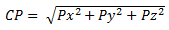
| CP |
Contact Pressure (b) |
| ILTXZ |
Interlaminar shear on XZ plane |
| ILTYZ |
Interlaminar shear on YZ plane |
(a) In some design codes and references, the Tresca equivalent stress is defined as twice the maximum shear stress which is equal to (P1 – P3), or else the stress intensity.
(b) Contact pressures are derived from the global nodal stresses by coordinate transformation. At each node, the solver reports the contact force. If the unit vector N along the direction of contact force is {Nx, Ny, Nz} in the global coordinate system, the nodal stress tensor is projected along the unit vector N to derive the three components of contact pressure {Px, Py, Pz} in the global coordinate system.
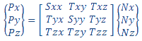
The magnitude of the contact pressure CP at each node is the square root of the sum of the squares of each component. The direction of contact pressure is always normal to the area of contact.