Use the Model Break View  tool to create configuration-based 3D break views (also known as interrupted views) of a model for individual drawing views.
You can create break views in a model of isometric orientation with traditional break shapes, including accurate depiction of pipe breaks. This allows angled parts and isometric drawing views to break correctly.
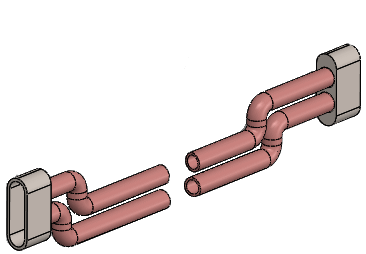 |
| Break in assembly |
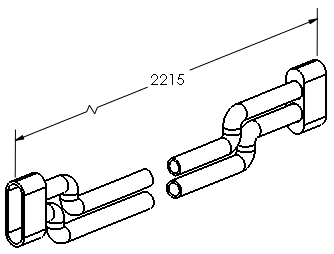 |
| Break in drawing |
To show a model break view within a drawing:
- Select the drawing view of a model that contains a model break view.
- Do one of the following:
- In the Drawing View PropertyManager, under Reference Configuration, select Show in exploded or model break state.
- Right-click the drawing view and click Properties. In the dialog box, in Configuration information, select Show in exploded or model break state, and click OK.