Using sketch points within a sketch, you can specify a feature pattern. The seed feature propagates throughout the pattern to each point in the sketch. You can use sketch driven patterns for holes or other feature instances.
To build a sketch driven pattern:
-
Open a sketch on the face of a part.
-
Create a seed feature on the model.
-
Click Point
 or , and add multiple sketch points to represent the pattern you want to create, based on the seed feature.
- Close the sketch.
- Click Sketch Driven Pattern
 (Features toolbar) or .
- Under Selections, do the following:
- Do one of the following:
- To create the pattern based on the feature, under Features to Pattern
 , select the feature in the graphics area.
If the feature to pattern includes fillets or other additions, use the flyout FeatureManager design tree to select these features.
- To create the pattern based on the faces that make up the feature, under Faces to Pattern
 , select all the faces in the graphics area. This is useful with models that import only the faces that make up the feature, and not the feature itself.
When using Faces to Pattern, the pattern must remain within the same face or boundary. It cannot cross boundaries . For example, a cut across the entire face or different levels (such as a raised edge) would create a boundary and separate faces, preventing the pattern from propagating.
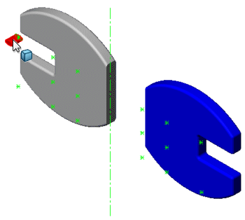
- To create a pattern based on multibody parts, under Bodies to Pattern
 , select the body to pattern in the graphics area.
 |
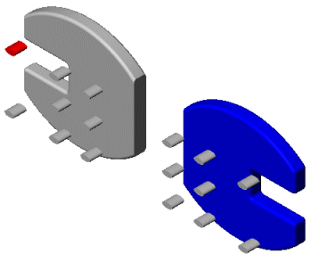 |
| Multibody part with Body to Pattern and sketch points
|
Sketch driven pattern applied |
- Under Options, set these options:
| Option |
Description |
|---|
| Geometry pattern |
Creates the pattern using only the geometry (faces and edges) of the features, rather than patterning and solving each instance of the features. The Geometry Pattern option speeds up the creation and rebuilding of the pattern. You cannot create geometry patterns of features that have faces merged with the rest of the part.
Geometry pattern is not available with Bodies to Pattern.
|
|---|
| Propagate Visual Properties |
Propagates SOLIDWORKS colors, textures, and cosmetic thread data to all pattern instances.
|
|---|
- Click
 .
.
 |
 |
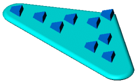
| Sketch pattern with Centroid as the reference point
|
Sketch pattern with Selected point as the reference point
|