Using X-Y coordinates, you can specify a feature pattern. Hole patterns using X-Y coordinates are a common application for table driven patterns. However, you can use other seed features, such as a boss, with table driven patterns. You can also save and load the X-Y coordinates of a feature pattern, and apply them to a new part.
To build a table driven pattern:
-
Create a seed feature.
- Create a coordinate system. The origin of this coordinate system becomes the origin of the table pattern, and the X and Y axes define the plane in which the pattern occurs.
- Click Table Driven Pattern
 (Features toolbar) or .
- In the dialog box, set these options:
| Option |
Description |
|---|
| Read a file from |
Imports a pattern table or text file with X-Y coordinates. Click Browse and select a pattern table (*.sldptab) file or a text (*.txt) file to import existing X-Y coordinates.
Text files used for table driven patterns must have only two columns: left for X coordinates and right for Y coordinates. The two columns must be separated by a delimiter such as a space, comma, or tab. You can use a combination of different delimiters within the same text file. Do not include any other information in the text file because this causes the import to fail.
|
|---|
| Reference point |
Specifies the point to which X-Y coordinates apply when placing pattern instances. The X-Y coordinates of the reference point are displayed as Point 0 in the pattern table. |
|---|
| Selected point |
Sets the reference point to the selected vertex or sketch point. |
|---|
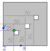
| |
Reference point: Selected point (upper left vertex of seed feature)
For each pattern instance, the selected upper-left vertex of the seed feature is placed at the X-Y coordinates specified in the table.
|
|---|
| Centroid |
Sets the reference point to the centroid of the seed feature.
|
|---|
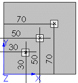
| |
Reference point: Centroid
For each pattern instance, the centroid of the seed feature is placed at the X-Y coordinates specified in the table.
The X-Y coordinates are measured from the origin of the coordinate system.
|
|---|
| Coordinate system |
Sets the coordinate system, including the origin, used to create the table pattern. Select the coordinate system you created from the FeatureManager design tree.
|
|---|
| Features to copy |
Creates the pattern based on features. You can select multiple features.
|
|---|
| Faces to copy |
Creates the pattern based on the faces that make up the feature. Select all the faces in the graphics area. This is useful with models that import only the faces that make up the feature, and not the feature itself.
When using Faces to Copy, the pattern must remain within the same face or boundary. It cannot cross boundaries . For example, a cut across the entire face or different levels (such as a raised edge) would create a boundary and separate faces, preventing the pattern from propagating.
|
|---|
| |
Boundary causes pattern to fail

|
|---|
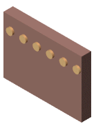
| |
Pattern succeeds without boundary
|
|---|
| Bodies to copy |
Creates the pattern based on multibody parts. Select the bodies to pattern. |
|---|
| Geometry pattern |
Creates the pattern using only the geometry (faces and edges) of the features, rather than patterning and solving each instance of the feature. The Geometry Pattern option speeds up the creation and rebuilding of the pattern. You cannot create geometry patterns of features that have faces merged with the rest of the part. Geometry pattern is not available with Bodies to Pattern. |
|---|
| Propagate Visual Properties |
Propagates SOLIDWORKS colors, textures, and cosmetic thread data to all pattern instances. |
|---|
| X-Y coordinate table |
Creates the location points for the pattern instances using X-Y coordinates. Double-click the area under Point 0 to enter the X-Y coordinates for each instance of the table pattern. The X-Y coordinates of the reference point are displayed for Point 0. Click  to undo coordinate table operations. to undo coordinate table operations. You can use positive or negative coordinates. To enter a negative coordinate, precede the value with a minus (-). You do not need to input X-Y coordinates if you imported a pattern table or text file.
|
|---|
- Click OK.