When selecting the constraints for a given part, you should consider the function of the selected features in the assembly. In many cases, feature function dictates the order in which you should apply constraints.
For example, features that are required to seat flush with one another are generally used as the primary constraint. Features used only to locate or orient a part in the assembly are often the secondary or tertiary constraint.
In addition to affecting the performance of an assembly, the order in which you apply the constraints can affect the results of a tolerance analysis.
These examples illustrate the effects constraint order can have on measurements.
Example 2
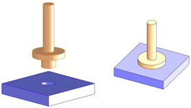
| Mate a flanged pin to a plate.
|
 |
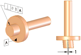
| The only tolerance is a perpendicularity you apply to the pin.
|
 |
| Constraint Scenario 1
|
|
|---|
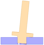
| For the primary constraint, use the pin. This constraint is applicable, for example, when the pin and hole form a press fit.
The pin and hole axes align concentrically. The face of the flange, datum plane A, acts as a stop to establish a single point of contact with the top of the plate.
Note the gap between the flange and the plate on the left side.
|
 |
| Constraint Scenario 2
|
|
|---|
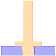
| For the primary constraint, use the plane of the flange. The plane mates flush with the plate, and the pin is centered within the hole.
The axis of the pin and hole are not concentric and the clearance hole must be large enough to accept the pin without binding.
|
 |