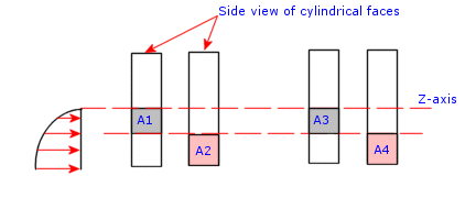
When you apply a bearing force to multiple faces, the software divides the force among the selected faces based on their areas and locations in the half-space (Φ less than or equal to 180º).
A bearing force is applied to the selected cylindrical faces as schematically shown in the figure. Keep in mind that the bearing force is applied normal to the face and that you can select circular shell edges too. Suppose that selected area A1=A2 and A3=A4. A2 will receive more force because of its maximum intensity location in the half-space. Similarly, A4 will get more force than A3. The ratio of the forces received by A1 and A3 is directly proportional to their areas since they occupy the same relative positions in the half-space. The same thing can be said for A2 and A4.

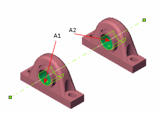
As illustrated in the following figure, if the selected areas A1 and A2 in the half-space and their relative positions with respect to the half-space are identical, the force will be divided equally.
