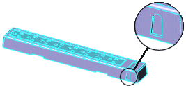
In this example, the recessed feature on the front of the plastic part is a trapped molding area that requires a core.
First, you create a sketch on a tooling solid (in this case, the
Cavity Body) to define the outline of the core. Then use the
Core 
tool to create the core.

To create a core:
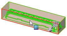
- Open a sketch on the inside face of the Cavity Body, as shown.

- Sketch the outline of the core you want to create.
 |
 |
| Front view |
Right view |
The plane on which you create a core sketch does not need to be perpendicular to the extraction direction of the core. In this case, the sketch is on the inside face of the cavity body, which is drafted 5° from the direction the core travels.
| Extraction
direction |
 |
Away from
extraction
direction |
- Close the sketch.
- With the sketch selected, click Core
 on the Mold Tools toolbar, or click .
- In the PropertyManager, set the options as described below, then click
 .
. A new body is created for the core and is subtracted from the
Cavity Body.

In the FeatureManager design tree, in the Solid Bodies folder  , the new core appears in the Core bodies folder
  .
.
Selections
Bounding sketch for core  |
Select the core sketch created in step 2. |
| Extraction direction |
Select the front face of the cavity body as shown.

|
Core/Cavity body  |
Displays the name of the cavity body. |
Parameters
Draft On/Off  |
Click to add draft, then set Draft Angle to 5. |
| Draft outward |
Select to create an outward draft angle. |
| End Condition |
Select Blind for the end condition in the extraction direction, then set Depth along extraction direction  to 50. to 50. |
| End Condition |
Select Blind for the end condition away from the extraction direction, then set Depth away from extraction direction  to 25. to 25. |
| Cap ends |
Select to define the end surface of the core. |