SOLIDWORKS Electrical Schematic
- Exercise #08
This exercise learns you to manage the PLCs. It is based on the electrical
project you made in the Exercise #07.
If you did not complete it, you can download the electrical project file
and unarchive it in
SOLIDWORKS Electrical.
If this is your first time, open the PDF file of the exercise to read
through it. Printing it out is recommended.
PLC management
Add a PLC with the following characteristics to the electrical project:
Brand: Schneider
Electric
Part: TWDLCDA16DRF
9 Digital inputs + 7 Digital outputs |
1. Open the PLC
management.

|
Menu: Electrical
project > PLCs |
2. Click on the Add
PLC icon and select the PLC manufacturer
part option.
|
PLC management > Add PLC >
PLC manufacturer part |
3. Allocate the requested part.
Input/Output
management
Create 9 digital inputs with the following designations: Sensor
#1 to Sensor #9 and 7 digital
outputs with the following designations: Solenoid
#101 to Solenoid #107
1. Select the PLC
management Inputs/Outputs
command.

|
PLC management > Inputs/Outputs |
2. Or select the Inputs/Outputs
command in the Electrical
project menu.
|
Menu: Electrical project
> Input/Output |
3. Select the Add
several Inputs/Outputs command using the Digital
PLC Input option in the Input/Output
management.

|
Inputs/Output management >
Add several Inputs/Outputs > Digital PLC Input |
4. Add 9 digital PLC inputs and 7 digital PLC outputs
in the same way.
5. To add a description, select the channel and click
on the Properties icon. You can
also click directly on the Description
box for the channel.
Save the digital inputs in a macro.
1. To create the PLC macro, select the inputs.
2. In the left-hand part of the Input/Output
management, select the User I/O
group.
3. Click on the Save
into macros icon to add the macro to the group you have just created.

|
Inputs/Output management
> Save into macros |
You can save the macro by storing it under a function. Upon
insertion, the Inputs/Outputs will automatically be grouped under
this function. |
Associate this I/O with the N1 PLC channels.
1. In the PLC management,
select the 9 Digital PLC inputs
and click on the Associate icon.

|
PLC management
> Associate I/O |
2. In the PLC management,
select the 9 Digital PLC inputs
and click on the Select icon.
A message will inform you of the consistency between the two selection
sets.
3. Repeat this operation for the Digital
PLC outputs.
Insert a page break between the inputs and outputs.
1. Open the PLC management.
|
Menu: Electrical project
> PLCs |
2. Choose the last Digital
PLC input and select the Add/Remove
a page break command in its contextual menu.
Editing
the macro associated with a circuit
In the PLC board drawing configuration, the circuits are associated
with a macro. Edit the macro associated with the Digital
input to replace the pressure sensor symbol by a thermal sensor
symbol.
1. Open the PLC drawing configuration.

|
Menu: Electrical project
> Configurations > PLC drawing...
Dockable panel > Contextual menu of electrical project: Configurations > PLC drawing... |
2. In the configuration dialog box, open the properties
of the configuration used in the electrical project (reminder: Electrical
project configuration > General tab).
3. Go to the Circuits
tab and in the Circuit type field
select Digital PLC input.
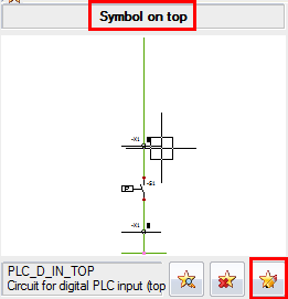
4. The module will be drawn in the upper part of the
drawing. In the Symbol on top
section, click on the macro modification icon.
5. The macro is automatically added to the dockable
panel, Pages tab and the macro
opens in the graphical area.
6. In the contextual menu of the symbol, select the
Symbol
> Replace command and select a pressure sensor symbol. Close the
macro.

|
Contextual
menu of symbol > Symbol > Replace |
The configuration is automatically updated. |
Generating
PLC drawings
Generate the PLC drawings and redirect them to a folder entitled PLCs and open the drawings to complete
them according to the appendix 8.
1. Open the PLC management.
|
Menu: Electrical project
> PLCs |
2. Select the Generate
drawings command.

|
PLC management > Generate
drawings |
3. In the Books/Folders
selection dialog box, select New folder
and create the PLC folder.
4. Select the folder.
The drawings are generated automatically. A message alerts
you to any problems that arise during generation. |
Complete the scheme in accordance with the Appendix 8A and 8B.