PLC design Configuration (IEC)

|
Menu: Electrical
project > Configurations > PLC drawing... > Properties
Menu: Electrical Project >
Configurations > PLC drawing... > New
Dockable panel > Contextual menu of electrical project: Configurations > PLC drawing... >
Properties
Dockable panel > Contextual menu of electrical project: Configurations > PLC drawing... >
New |
A PLC drawing configuration file groups all the PLC file layout settings.
You can create as many configurations as you wish. The configurations
are grouped in the PLC
configuration management.
The configuration file dialog box is divided into two parts. The top
part illustrates the settings displayed in the lower part. When you select
a setting, the graphics display the correspondence in red.
Several tabs group the settings by theme.
General
Name: The name of the configuration
file.
Description: Enter a description
in all languages supported by the software.
Size
General
All numeric values use the unit system set in the electrical project
configuration.
Orientation: Select the direction
of the module drawing. In Horizontal
mode, the module can be inserted at the top or bottom of the drawing.
In Vertical mode, it can
be inserted on right or on left.
Size
Symbol height: Enter the height
of the module.
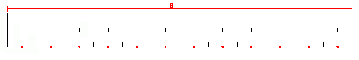
Maximal length of symbol in a drawing:
Enter the length of the module.
Channels
Channel separator height: Enter
the length of the vertical line separating 2 PLC channels.
Channel width: Enter the width
of the channel.
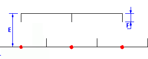
Combs
Comb height: The comb is the
graphic element grouping channels. Enter the distance between the bottom
of the module and the horizontal line of the comb (E).
Comb tooth height: Enter the
height of the vertical line of the comb (F).
Attributes
This tab allows you to manage the location of the attributes to be inserted;
these attributes can also be edited.

|
Opens the symbol selector to select the desired symbol. |

|
Removes the symbol. |

|
Opens the symbol editor to modify it. |
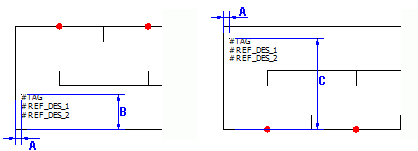
Information (Left)
X coordinate: Enter the distance
between the vertical line of the module and the insertion point of attributes.
These attributes have a left justification (A).
Y for bottom symbol: Enter the
distance between the horizontal line of the module and the insertion point
of attributes for a module symbol inserted at the bottom of the drawing
(B).
Y for top symbol: Enter the
distance between the horizontal line of the module and the insertion point
of attributes for a module symbol inserted at the top of the drawing (C).
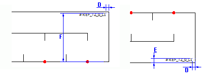
Information (Right)
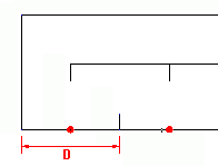
X coordinate: Enter the distance
between the vertical line of the module and the insertion point of attributes.
These attributes have a right justification (D).
Y for bottom symbol: Enter the
distance between the horizontal line of the module and the insertion point
of attributes for a module symbol inserted at the bottom of the drawing
(E).
Y for top symbol: Enter the
distance between the horizontal line of the module and the insertion point
of attributes for a module symbol inserted at the top of the drawing (F).
Layout
Allows you to manage the PLC module drawing layout settings.
Settings in the General section
are available only for vertical representation of the module (set on the
Size tab).
General
Options: (Available only for
a vertical drawing) You can draw one or more modules per drawing. Select
the option you want.
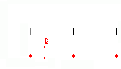
Column size: If you select One symbol per column in the previous
parameter, enter the size of the column. The preview displays a vertical
line to show this value.
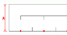
Symbol insertion point
X coordinate: Enter the X coordinate
corresponding to the insertion point of the module (A).
Y for top symbol: Enter the
Y coordinate corresponding to the insertion point of the module when the
module is drawn at the top of the drawing (B).
Y for bottom symbol: Enter the
Y coordinate corresponding to the insertion point of the module when the
module is drawn at the bottom of the drawing (C).
Connection points
Allows you to define the symbol used to propagate the terminal number.
This symbol must contain the attribute #P_TAG_0.
|
Opens the symbol selector to select the desired symbol. |
|
Removes the symbol. |
|
Opens the symbol editor to modify it. |
Circuits
These settings allow you to define symbols and macros associated to
a type of circuit for a graphical representation at the top or bottom
of the drawing.
Circuit type / Direction: These
settings allow you to define the direction in which the module is drawn
(insertion in the top or bottom part of the module). SOLIDWORKS Electrical
examines the module circuits in the order that they appear in the PLC management. The module circuit
is compared with the circuits in the configuration list. As soon as the
circuits match, SOLIDWORKS Electrical
saves the setting you have selected (Undefined,
Top or Bottom)
and uses it to insert the module. If you choose Undefined
for a circuit, SOLIDWORKS Electrical
will move on to the next circuit until it finds a circuit for which Top or Bottom
mode has been selected.
Example 1:
The first circuit for the module is Digital PLC output. If you select
Digital PLC output in the configuration
list and you select Bottom mode,
the module will be inserted in the lower part of the drawing.
Example 2:
The first circuit for the module is Power supply. It is not possible
to tell from this type of circuit if the module will be inserted in the
top or bottom part of the drawing. You must therefore select the Undefined mode for Power
type circuits. In this way SOLIDWORKS Electrical
will move on to the next circuit until it meets a circuit for which you
have selected Top or Bottom
mode.
Delete circuit type association:
This button allows you to dissociate a symbol or macro from the circuit,
or to delete the existing associations.
PLC channel pattern symbols:
Allows you to select the symbols representing the inside the module for
insertion in the top or bottom part of the drawing. These settings are
associated with the circuit selected in the list.
Macro connected to channels:
In addition to automatic generation of the module drawing, SOLIDWORKS Electrical
allows you to automatically generate the diagram connected to the module
for insertion in the top or bottom part of the drawing. A macro can be
associated with each type of circuit.
File data
This tab allows you to define the parameters for the automatic generation
of information to be transferred to the properties of PLC drawing. Clicking
the column allows you to open the Formula
management.
Description: Allows you to define
the parameters for the automatic generation of data to be transferred
to the description of the PLC drawing.
User data/Translatable data:
Allows you to set the parameters for the automatic generation of data
to be transferred to the user data of the PLC drawing.