Location outlines
The dockable panel displays additional options.
A drop-down list allows you to select the type of outline (Thin, Double
and Filled).
When the Zig-Zag box is checked,
SOLIDWORKS Electrical
inserts a "zig-zag" line on the lower line of the rectangle
representing the fact that the whole location is not drawn. This option
is not available on location outlines drawn in the form of polylines.
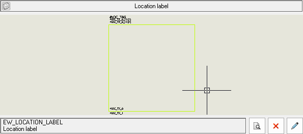
The checkbox Location label
allows you to insert the symbol displayed in the dockable panel. This
symbol corresponds with the symbol saved in the electrical
project configuration; if you want to insert another symbol, click
Other symbol.
A location label is automatically placed in the top part of the outline.
The location labels are represented by a symbol
and attributes which can display the data or properties
attached to the location. The location labels have a contextual menu allowing
you to, among other things, edit the location properties.
Configuration of the symbol to be used

|
Electrical project settings: Symbol
tab |

|
Opens the symbol selector to select the desired symbol. |

|
Removes the symbol. |

|
Opens the symbol editor to modify it. |
Symbols representing location labels do not have circuits or connection
points. In symbol properties
select Location labels in the
Symbol type parameter.