The Warp analysis module predicts the final shape and dimensions of the part, as well
as the de-molding residual stresses, after the part has fully cooled.
The Warp module uses residual stress results from the Fill and Pack modules.
Unlike the finite volume flow analysis used in Fill and Pack, the Warp analysis is based
on the finite element method. The Warp analysis considers the plastic part as a linear
elastic body that can sustain small deformations.
You can exclude gates and runners from Warp to focus only on the trimmed
cavity part. The Warp module automatically excludes the mold, cooling channels, and
filled hot runners.
After running a Warp analysis, you can display the deformed shape of the
part with a scale factor to emphasize the effects of the deformation. You can also view
displacement results in the X-, Y-, or Z- direction, or define a reference location or
reference plane that is used as the baseline to measure deformation.
Warp Analysis Steps
| 1 |
Define the process parameters:
- Ambient temperature
- Gravity direction
|
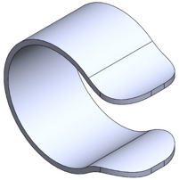
CAD geometry of a
part |
| 2 |
Create the mesh and select
materials |
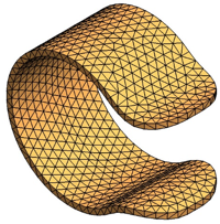
Surface mesh
|
| 3 |
Run the analysis |
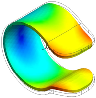 Result plot of
total displacement showing deformed geometry
|
An alternative way to compute warpage is to export the part to
SOLIDWORKS Simulation together with the de-mold residual stress results. You can
export the deformed part shape as a SOLIDWORKS part body or as tessellated
surfaces.