A component represents an electrical device, a PLC, a connector, or a terminal. It is
represented by one or several symbols and has a mark. A component can be present in your
electrical project without having a graphical representation. No symbol needs to be inserted
into the drawings.
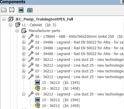
The electrical component tree has a new node to group all the manufacturer parts of
the location.
Components are listed in a specific tab on the dockable panel. When you double-click
a symbol of a component, it opens the drawing in which the symbol is inserted.
Displaying Components
You can use the [F5] key or the Refresh command, in the
context menu of the electrical project, to refresh the component list. From the
context menu of the electrical project, click the View
submenu to view the different modes of the component list.
| Option |
Description |
| Location view/ Function
view |
This mode allows you to display the components
grouped by location or by function. |
| Child components by hierarchy / Child
components in real location (function) |
This option allows you to display a child
component under its parent, or under its real location (function)
when the location (function) of the child component is different
from that its parent. |
| Manufacturer parts |
Controls the visibility of the tree items for the
manufacturer parts. Choose from the following three options:
- Hide.
Hides the new node for manufacturer parts. The tree items
relative to the manufacturer parts appear directly under the
component.
- With
graphics. Creates intermediate tree items
only for the manufacturer parts that have graphics (2D
footprints, connection labels, etc.) associated with it.
This is the default option.
- All.
Creates items for all the manufacturer parts whether they
have graphics associated with them or not.
|
| Sort by function (location) / Sort by
mark |
Allows you to sort the components by the mark or
by the location (function). |
| In terminal strip and PLC, sort by
position / Always sort by mark |
This option impacts only PLC and terminal strips.
It allows you to sort the subcomponents of a terminal strip or a
PLC, by the mark or the position. |
| Hide accessory
terminals |
Allows you to hide the accessories
terminals. |
Adding a New Component
A component can be added from a location context menu, or from existing components,
where one component is dependent on another.
- Component
 : If you select the
Component option, only one mark
is added if you have not selected a manufacturer part. The component
properties dialog opens, letting you manage the component mark and if you
want to assign it to a manufacturer part.
: If you select the
Component option, only one mark
is added if you have not selected a manufacturer part. The component
properties dialog opens, letting you manage the component mark and if you
want to assign it to a manufacturer part.
- Component from a manufacturer part
: Selecting the
Manufacturer part option opens a dialog box where you can select a
manufacturer part.
According to the equipment chosen and
especially the classification it relates to, a mark is automatically
generated and added to the components list. You can also manage the
number of components you want to create. At the Manufacturer part selection dialog box
closure, enter the number of components and validate. To create a new
component, click OK (Continue).
The Manufacturer part selection dialog box reopens to search a new
manufacturer part.
Setting a Permanent Component
Generally, when all the graphical elements (symbol, 2D footprint) are deleted, the
component is removed. You can activate a special property on the component to keep
it in the component list.
Click  , to access this permanent component setting
is available in its context menu. The icon is different on components with the
option enabled.
, to access this permanent component setting
is available in its context menu. The icon is different on components with the
option enabled.
Deleting a Component
The delete command  is available through the
component context menu. A component inserted into a drawing cannot be deleted.
is available through the
component context menu. A component inserted into a drawing cannot be deleted.
Component Properties
A component can be modified by using the context menu Properties command  or the Properties of the
component for a symbol. It gives you access to the component
properties dialog, where you can modify the mark and associate manufacturer parts.
For more information, see Component Properties.
or the Properties of the
component for a symbol. It gives you access to the component
properties dialog, where you can modify the mark and associate manufacturer parts.
For more information, see Component Properties.