Applying Restraints

You fix one of the plate edges (Edge 3 in the figure below) in all directions except rotation about the Z-axis. You apply symmetry restraints to the two edges that define the cut boundaries of the quarter plate (Edge 1 and Edge 2 in the figure below).
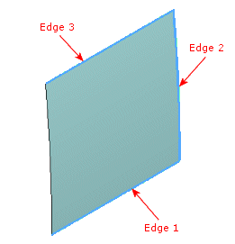
To fix Edge 3 in all directions except rotation about the Z-axis:

  1. In the nonlinear study tree, right-click the Fixtures icon, and select Advanced Fixtures.
  2. Select Use Reference Geometry.
  3. For Faces, Edges, Vertices for Fixture, select in the graphics area the Edge 3 as shown in the figure above.
  4. For Face, Edge, Plane, Axis for Direction , select Front Plane from the flyout FeatureManager design tree.
  5. In the Translations and Rotation boxes, select all components to set to zero, except the Normal to Plane under Rotation.
  6. Click .