The program automatically creates a mixed mesh when different geometries
exist in the model. Redefine the mesh settings as you cannot copy the mesh from the
SheetMetal_Study.
-
In the Simulation study tree, right-click Mesh
 and select Create Mesh
 .
.
-
In the PropertyManager, under Mesh
Parameters, set Global
Size
 to 0.5 in.
-
Under Options, select
Run (solve) the analysis.
-
Click
 .
.
-
In the Linear Static
dialog box, click No when prompted to
solve with the large displacement flag activated.
After the analysis completes, obtain the resultant
displacement plot. Unit is inches (in).
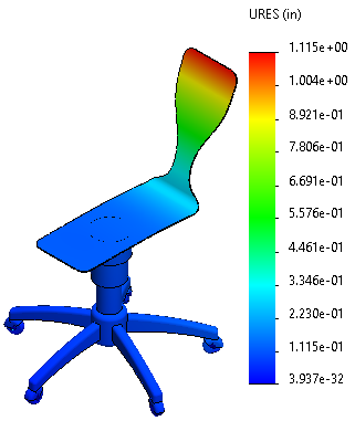
The
results obtained by modeling the seat with shell elements closely agree with
those obtained from the study where all parts of the assembly are modeled
with solid elements.
Congratulations! You have completed this lesson.