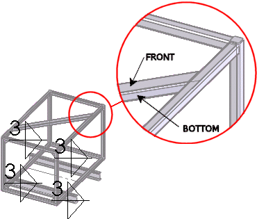
To create a drawing view of a single body from the weldment part, you select the body and define the view orientation in the part document, then return to the drawing document to place the view. Create a view of the rectangular cross member.
-
Select the drawing view.
-
In the drawing document, click Relative View
 (Drawing toolbar).
If you are asked to use the auto-saved version
of the part, click Yes.
The part document opens.
If the part
document does not open, right-click in the graphics area and click
Insert from file. Select the part document and
click Open.
- In the PropertyManager, under Scope:
- Select Selected Bodies.
-
In Bodies for creating
view
 ,
pick the cross member in the graphics area.
- In the PropertyManager, under Orientation:
- Select Front in First orientation, then select the face shown for Face/plane for first orientation.
- Select Bottom in Second orientation, then select the face shown for Face/plane for second orientation.
This selects the rectangular cross member and defines the front and bottom orientations of the drawing view.

-
Click
 .
.
The display changes back to the drawing document.