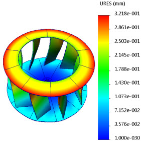
Cyclic symmetry is supported for nonlinear studies.
Available for SOLIDWORKS Simulation Premium.
In the Fixture PropertyManager under Advanced, select Cyclic symmetry  .
.
The cyclic symmetry constraint is appropriate for simulations of models where the geometry, restraints, and loading conditions are repeated in a cyclical pattern with reference to a central axis.
After you run the nonlinear analysis, you can display results on the full model. In the PropertyManager of the desired result quantity, under Advanced Options, select Display symmetric results.
 |
 |
| Displacement results shown for a part with applied cyclic symmetry constraints. |
Displacement results shown for the entire model with active option Display symmetric results. |
For circular symmetry, the angle between the selected faces must be evenly divisible into 360. The axis of symmetry must lie at the intersection of the two selected planes where you apply the cyclic symmetry.
To set up your model for applying cyclic symmetry restraints, you create a cut (or an assembly cut feature) to produce a section of the model that can be repeated in a cyclical pattern about a central axis of revolution. A valid cut section produces a complete part, when it is repeated with an equal spacing circular pattern feature, and there are no gaps or interferences between the sections. You cannot apply a cyclic symmetry restraint to an invalid section.