The Chamfer PropertyManager has been updated to align with the Fillet tool. There are two new chamfer types, Offset Face and Face Face, which you can convert from chamfers to fillets and back.
Offset Face Chamfers
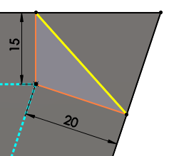
Offset face chamfers are solved by offsetting the faces adjacent to selected edges. The software calculates the intersection point of the offset faces, then calculates the normal from that point to each face to create the chamfer.
 |
 |
| Calculation of chamfer offset |
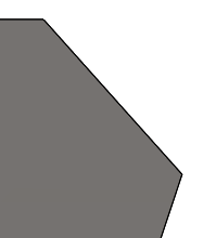
Chamfer applied |
This method yields predictable results when chamfering between non-planar faces. Offset face chamfers can change direction on an edge-by-edge basis, and they support chamfering entire features and surface geometry.
Face Face Chamfers
Face face chamfers can create symmetric, asymmetric, hold line, and chord width chamfers.