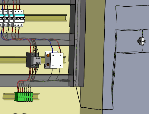
Route Wires
Routing wires consists of generating a 3D representation of the wire
path within your electrical installation.
The routing is made possible thanks to the routing
paths and connection points on the components.
Segregation manages
the rules applying to the paths of the wires.
Routing wires refers to routing
the wires and cable cores.

|
SOLIDWORKS Electrical 3D
menu: Route Wires
Menu: Tools > SOLIDWORKS Electrical
> Route Wires |
When the command is launched, the left dockable panel changes to display
the options of the command.
Several of these parameters are saved in the SOLIDWORKS Electrical
file, they are specific to the file. The others are saved in the registry
and they are common to all SOLIDWORKS Electrical
files.
Routing Analysis
Show errors: This option,
when activated, displays a report at the end of the routing. This report
shows all routing errors. Click the Help
button on a line of the report to obtain information about the error.
Select route type
SOLIDWORKS
Route: Routes the wires as managed
by SOLIDWORKS,
taking into account the diameter of the wires.
3DSketch Route: Routes the wires
in the form of a 3D sketch. This mode is quicker and more preferable if
the routing is not permanent.
Select renderer type
Use splines: Ensures an optimal
rendering of the wire routing by using curves (splines). When you use
splines in the routing path, you can manually add points on it to improve
the routing.
Use lines: Generates wire routing
by using straight lines. When this mode is selected, the Add
Tangency check box allows curves to be automatically generated
at the end of the straight lines.
Components to route
All components: Launches routing
across all components present in the assembly.
Selected components: Launches
routing across a section of the components. Select the components in the
graphical area. Only the wires connected to this selection of components
will be routed.
Routing parameters
The first parameter allows you to enter the distance between two routing
paths.
The second parameter allows you to enter the distance between a connection
point and a routing path.
The third parameter lets you manage the distance between two wires.
The graph allows you to quickly view connections between components.
There are two buttons available: one for display, and the other for deletion.
