Beam elements can resist bending, shear, and torsional loads. The typical
frame shown below is modeled with beams elements to transfer the load to the supports.
Modeling such frames with truss elements fails since there is no mechanism to transfer
the applied horizontal load to the supports.
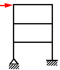
Beam elements require defining the exact cross section so that the program
can calculate the moments of inertia, neutral axes and the distances from the extreme
fibers to the neutral axes. The stresses vary within the plane of the cross-section and
along the beam.
Consider a 3D beam with cross-sectional area (A) and the associated mesh.
Beam elements can be displayed on actual beam geometry or as hollow cylinders regardless
of their actual cross-section shape.
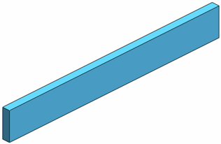 |
| 3D geometry |
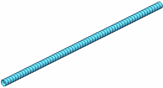 |
| Mesh on Cylinders (each hollow
cylinder is an element) |
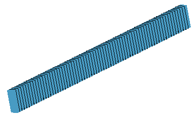 |
| Mesh on Beam Geometry |
Now, the figure below shows a small segment along a beam element
subjected to simplified 2D forces (axial force P, shearing force V, and bending moment
M):
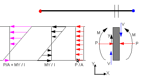
In a general case 3 forces and 3 moments act on the segment.
Uniform axial stress = P/A (similar to truss elements)
Uniform shearing stress = V/A
The bending moment M causes a bending stress that varies linearly with
the vertical distance y from the neutral axis.
Bending stress (bending in y direction) = My/I, where I is the moment of
inertia about the neutral axis.
The bending stress is the largest at the extreme fibers. In this example,
the largest compression occurs at the top fiber and the largest tension occurs at the
extreme bottom fibers.
Joints
A joint is identified at free ends of structural members and at the
intersection of two or more structural members. The Edit Joint PropertyManager
provides a tool to help you define joints properly. The program creates a node at
the center of the cross section of each joint member. Due to trimming and the use of
different cross sections for different members, the nodes of members associated with
a joint may not coincide. The program creates special elements near the joint to
simulate a rigid connection based on geometric and material properties.
Material Properties
The modulus of elasticity and Poisson's Ratio are always required.
Density is required only if gravitational loads are considered.
Restraints
You can apply restraints to joints only. There are 6 degrees of
freedom at each joint. You can apply zero or non-zero prescribed translations and
rotations.
Bonding
In a study with beams, solids and shell surfaces, you can bond beams
and beam joints to solid and shell faces.
Bonding between touching structural members with a surface or sheet
metal face is automatically created.
Beam Stiffeners for Curved Surfaces
You can bond beams (straight or curved) that act as stiffeners to
curved surfaces of shells or sheet metal bodies.
The software automatically bonds beams to curved surfaces that have
touching geometries or are situated within reasonable clearance. The program uses
beam element sizes compatible with the surface mesh sizes. The feature is available
for static, frequency, and buckling studies.
Loads
You can apply:
- Concentrated forces and moments at joints and reference points.
For dynamic studies, you can apply time-dependent or frequency-dependent
loads.
- Distributed loads along the whole length of a beam.
- Gravitational loads. The program calculates gravitational forces
based on the specified accelerations and densities.
- Uniform or selected base excitation for dynamic studies.
- Initial conditions for dynamic studies. Apply an initial
displacement, velocity, or acceleration (at time t=0) at joints or beam
segments.
Meshing
A structural member is automatically identified as a beam and meshed
with beam elements. After you create the mesh, you can apply mesh controls to
specify a different number of elements or element size for selected beams.
Beam and truss members can be displayed on actual beam geometry or as
hollow cylinders regardless of their actual cross-sectional shape.
Results
Results for each element are presented in its local directions. You
can view uniform axial stresses, torsional, bending and shear stresses in two
orthogonal directions (dir 1 and dir 2), and the highest stresses on extreme fibers
generated by combining axial and bending stresses.
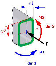
A beam section is subjected to an axial force P and two moments M1
and M2 as shown below. The moment M1 is about the dir 1 axis and the moment M2 is
about the dir 2 axis.
When you select the option Render beam
profile (Stress Plot PropertyManager), the software calculates
stresses that vary within the plane of the cross-section. Stresses are calculated at
both ends of each mesh element, and also at points of the cross-section with varying
distance from the beam's neutral axis.
When the option Render beam
profile is cleared, the software calculates the stress values at the
extreme fibers of each beam end. It reports the stress value with the highest
magnitude for each beam segment.
| Axial |
Uniform axial stress = P/A
|
| Upper bound bending in DIR
1 |
Highest magnitude of bending
stress due to moment M1 (Bending
Ms/Ss in the plot name, title, and legend) . |
| Upper bound bending in DIR
2 |
Highest magnitude of bending
stress due to moment M2 (Bending
Mt/St in the plot name, title, and legend). |
| Upper bound axial and
bending |
The software calculates the highest stresses at
the extreme fibers of the cross-section, by combing the uniform
axial stress and the two bending stresses due to M1 and M2 This
is the recommended stress to view. The stress values are
calculated at both ends of each mesh element:
P/ A + [(M1* I22 + M2 *
I12) * y1 + ( M2 * I11 + M1 *
I21) * y2)] / (I22 * I11 - I12^2)
where I ij (i = j = 1
or 2) are the moments of inertia about the respective local
orthogonal beam directions 1 and 2.
|
When probing beam results, ignore any nodes that appear in the middle of beams and
are located outside of the beam's cross section. The software internally calculates
these reference mid-nodes to define the orientation of the beam's local orthogonal
directions 1 and 2. To view the three local orthogonal directions of a beam, in the
Apply/Edit Beam PropertyManager, click Show beam
direction.