You use the planar mapping option to project a common 0º reference to a group of faces or surface bodies.
To use the planar mapping option, in the Simulation study tree, right-click a shell icon and select Edit Definition. In the PropertyManager, under Type, select Composite and under Composite Options, select Planar Mapping.
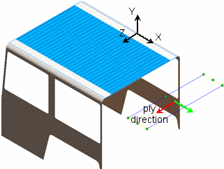
You can use one of the three orthogonal XY, YZ, or XZ planes for defining the projection direction. For example, the image shows the roof of a car frame model using the XZ plane for planar mapping. In general, the projection plane must be parallel to the shell face.

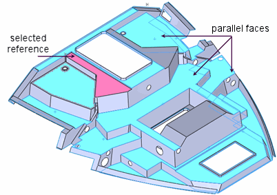
You can also use a reference face or edge to define the projection direction. For example, in the boat tray model, you can use one of the parallel shell faces as Selected Reference to project the 0º reference to the other faces.
