Defines a beam or truss, joint conditions, and section properties of the selected beams. For beams, you control the transfer of forces and moments to each end. This allows you to release (set to zero) any of the force and moment components at the end. Note that restraints apply to joints and hence to all beam ends that meet at the joint.
The options specified here override restraints. For example, if you define a beam end as a Hinge and apply a Fixed restraint to the associated joint, the specified beam end acts as a Hinge and does not carry any moment.
In the Simulation study tree, right-click a beam definition and click Edit Definition.
Type
Sets the type of the element for the selected structural
members.
| Beam |
A beam element resists axial,
bending, and torsional loads. |
| Truss |
A truss element can resist axial
loads only, similar to an axial spring. |
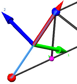
| Show
beam direction |
Toggles the visibility of the beam
directions in the graphics area. The red arrow shows the positive
axial direction, the green arrow shows the positive direction 1, and
the blue arrow shows the positive direction 2 for the selected
beams.
|
Beam
forces and
stresses are listed with respect to the beam's
local coordinate system. Beams or trusses under axial compressive loads show a
negative axial beam stress value and beams under axial tensile loads show a positive
axial beam stress value.
End1 Connection
Sets the forces and moments at End 1  of the
beam. Used for beams only.
of the
beam. Used for beams only.
End 1
and End 2

of the beam are highlighted in the graphics area in
different colors.
| Rigid |
No forces or moments are released
at this end. If restraints are applied to the associated joint, the
restraint condition fully defines the transfer of forces and
moments. If no restraints are applied, continuity is assumed at the
associated joint. Use this option unless there is a reason to
release (set to zero) force or moment components at this
end. |
| Hinge |
The end can rotate freely and does
not transfer any moments to the joint. Apply this condition to all
beam ends meeting at a joint to define the joint as an intermediate
hinge. |
| Slide |
The end can translate freely and
does not transfer any forces to the joint. |
| Manual |
For each force and moment
component, specify whether it is known to be zero manually.
|
Hinge- 1st direction
|
Select this option to set the moment
about the first direction of the cross section to zero.
The end can rotate about this direction.
|
|
Hinge- 2nd direction
|
Select this option if the moment about
the second direction of the cross section is known to be
zero. The end can rotate about this direction.
|
|
Hinge- Along beam
|
Select this option if the moment about
the axial direction of the beam is known to be zero. The
end can rotate about this direction.
|
|
Slide - 1st direction
|
Select this option if the force in the
first direction of the cross section is known to be
zero. The end can translate along this direction.
|
|
Slide - 2nd direction
|
Select this option if the force in the
second direction of the cross section is known to be
zero. The end can translate along this direction.
|
|
Slide - Along beam
|
Select this option if the force in the
axial direction of the beam is known to be zero. The end
can translate along this direction.
|
|
End2 Connection
Sets the forces and moments at of the beam.
Options are similar to .
Section Properties
For structural members that use weldment profiles from the SOLIDWORKS
database, Simulation calculates the section properties. For tapered beams, after
meshing the beam bodies, Simulation calculates the section properties at selected
cross sections across the beam's length. For custom beam profiles, enter the
user-defined section properties.
The Beam Details dialog box
lists the section properties of a beam. Right-click a beam body, and click
Details.
| Units |
Unit of length for the calculation
of torsional constant and distance for maximum torsional shear.
|
| Torsional Constant (K) |
Displays the torsional stiffness
constant (length to the fourth power). The torsional constant is a
function of the beam's cross section. The
software calculates the torsional constants for most of the beam
profiles. For formulas of torsional constants for various cross
sections, see reference Formulas for
Stress and Strain, Roark and Young, Chapter 9, Table
20.
|
| Distance for Max Shear (CTOR) |
Maximum distance from the shear center of the
section to the furthest point on the cross section (radius ot
the circumscribed circle centered at the shear center). 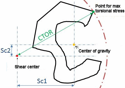 The maximum torsional shear stress is then
calculated from: τ max = (T / K)* CTOR, where T is the applied
torque.
|
| Shear
Factor |
The shear factor accounts for the
nonuniform shear stress distribution across a beam's cross section
and is considered for the calculation of a beam's shear deformation.
Its value depends on the shape of the cross section and the
Poisson's ratio of the material assigned to a beam. Simulation derives the shear factor of beams
that have arbitrary cross sections based on the numerical method
described in Isoparametric Elements for
Cross-sectional Properties and Stress Analysis of Beams, by
Karan S. Surana, International Journal for Numerical Methods
in Engineering, Vol 14, 475-497 (1979). For most beams with rectangular cross
sections, the shear factor is 5/6. For rectangular beams
with varying height to depth ratios and varying Poisson's
ratio values, shear factors can differ from 5/6. See the
following table for reference.
|
| Reset |
Resets the variables to their
default values. |
The following table lists shear factors for rectangular beams with varying height to
depth ratios and Poisson's ratios (v).
Reference: Shear correction factors in Timoshenko’s beam
theory for arbitrary shaped cross-sections, by F. Gruttmann and W. Wagner,
Computational Mechanics, Vol 27, 199-207 (2001)
| Height to Depth Ratio |
Poisson's ratio, v = 0 |
Poisson's ratio, v = 0.25 |
Poisson's ratio, v = 0.5 |
| 2 |
0.8333 |
0.8331 |
0.8325 |
| 1 |
0.8333 |
0.8295 |
0.8228 |
| 0.5 |
0.8333 |
0.7961 |
0.7375 |
| 0.25 |
0.8333 |
0.6308 |
0.4404 |