Hide Table of Contents

Render Tab

The Render tab lets you control scene lighting and rendering characteristics.

This page discusses:

Mode Commands

Render mode commands let you choose model display characteristics.

Icon Command Name Description
Mode Specifies the render mode, which determines display characteristics such as lighting and color.

See Render: Mode Commands below.

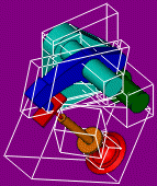
Show/Hide Bounding Boxes

(Listed under Mode .) Displays minimum bounding boxes around actors.
DisabledEnabled

Outline Style

Specifies the outline style for render modes that support outlines, such as Smooth with Outline and Technical.

See Render: Outline Style Commands below.

Render: Mode Commands

Custom rendering lets you set different rendering modes for individual geometry actors. You can also configure visible and hidden line styles in vector output. Configure custom rendering from the Custom rendering category in the Properties pane.

IconRender Mode Example Lighting Outlines Silhouette Lines Color Source
Custom Mode-specific Mode-specificMode-specificMode-specific
Smooth Yes *No NoActor
Smooth with Outline Yes *Yes No Actor
Shaded Illustration Special **Yes Yes Special (White)
Shaded Illustration with Color Special **Yes Yes Actor (Attenuated)
Shaded Illustration Without Silhouette Special **Yes No Special (White)
Technical Yes *Yes Yes Actor
Flat Technical No Yes Yes Actor
Silhouette No Yes Yes None
Flat Yes *No No Actor
Wireframe Yes *No No Actor
Points Yes *No No Actor

Legend:

  • * Supports predefined lighting modes (Soft, Medium, ...)
  • ** Internal colored soft lighting. Not configurable (no properties).

Note: When one or more cutting planes are enabled, Custom render mode and modes with silhouette lines (such as Shaded Illustration and Technical) display as Smooth with Outline.

Render: Outline Style Commands

Icon Outline Style Description Example
Sharp Edges Draws significant model edges only as determined by the Minimum angle document and actor properties.
Construction Edges Draws surface construction lines in addition to sharp-edge lines. Construction edges are the boundaries between faces (as defined in some CAD formats).
Smart Outlines Draws center lines for some circular fillets (depending on fillet angle and length) in addition to sharp-edge lines.
Note: Smart-outline generation can be time intensive.

Depth of Field Commands

Depth of Field (DOF) commands let you enable the DOF effect and set the focal point.

Icon Command Name Description
Enable Depth of Field

Enables the DOF effect. Portions of the scene away from the camera focal point appear blurred. For details, see Depth of field in the Properties pane.

Note: Requires Advanced OpenGL hardware acceleration.
Disabled Enabled

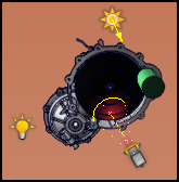
Set Depth-of-Field Focal PointLets you place the DOF focal point in your scene. At the focal point, there is no blur. To set the focal point, click this command and then click a geometry actor in the viewport. The focal point is associated with the actor; moving the actor moves the focal point. To set the focal point without actor association, click in empty viewport background or press Alt before clicking an actor. The focal-point icon is red when associated with an actor and white otherwise.
Tip: You can also change the focal point by dragging the icon in the viewport.
Show/Hide Depth-of-Field Focal Point (Visible)

Displays the DOF focal-point icon in the viewport.

Note: Enabling Automatic or using Set Focal Point also enables Visible.
Disabled Enabled

Set Depth-of-Field Focal Point Automatically (Automatic) Changes the DOF focal point each time you rotate or pan the viewport. To disable the automatic behavior, clear this option. To set the focal point manually, use Set Focal Point (which also disables Automatic).

Lighting Commands

Lighting commands let you control how your model is illuminated. You can select from several standard (predefined) lighting modes, create custom light sources, and apply lighting effects.

Icon Command Name Description
ModeDefines the number and type of lights used to illuminate your 3D scene.

See Lighting: Mode Commands below.

Create

Creates custom (user-defined) light sources.

See Lighting: Create Commands below.

Enable Per-Pixel Lighting Displays shaded surfaces based on the color and illumination at each pixel. For details, see the Per-pixel lighting viewport property.
Note: Requires Advanced OpenGL hardware acceleration.
Enable Shadows

Makes all geometry actors cast and receive shadows, making rendering for lighted scenes more realistic. For details, see the Shadows viewport property.

Note: Shadows requires per-pixel lighting. Enabling Shadows also enables Per-pixel Lighting .

Enable Ambient Occlusion Enables the ambient occlusion lighting effect. For details, see the Ambient occlusion viewport property.
Note: Requires Advanced OpenGL hardware acceleration.
Enable Glow Enables the glow lighting effect. For details, see the Glow viewport property.
Note: Requires Advanced OpenGL hardware acceleration.

Lighting: Mode Commands

Icon Command Name Description
CustomSpecifies that model lighting is determined by the spot, directional, and positional lights you have created. To use standard lighting modes, clear this option.
Soft (1 Light) Selects a predefined lighting mode consisting of one, two, or three light sources from different directions and with varied lighting characteristics.
Medium (2 Lights)
Metal (3 Lights)
Heavy Metal (3 Lights)
High Contrast
Shaded Illustration (Cool & Warm)
Default (2 Lights)
Light

Turns on or off scene lighting (custom or predefined lighting mode). When lighting is off, ambient lighting comes from all directions, colors are flat, and there are no shadows.

DisabledEnabled

Lighting: Create Commands

Icon Command Name Description
Create Spot LightCreates a light source with a focused, cone-shaped beam that is brightest at its center. To create a spot light, activate this tool, click to place the light origin, click the target, and then move the mouse to change the beam size and click again. Press Esc to exit the tool.
Create Directional LightCreates a light source that produces parallel rays from a single direction as though the source were placed infinitely far away from the model. To create a directional light, activate this tool, click to place the light origin, and click again in the direction of the light beam. Press Esc to exit the tool.
Create Positional LightCreates a light source at a specific coordinate in the model space that emits light in all directions. To create a positional light, activate this tool, and then click to place the light origin. Press Esc to exit the tool.


Notes:
  • Custom light sources are active in Custom lighting mode only.
  • Set light properties, such as intensity and color, from the Properties pane.
  • A model can have a maximum of 12 simultaneous active light sources.
  • Light types have different icons in the viewport: spot , directional , and positional .
  • Lights can be animated.
  • Light actors are listed in both the Collaboration pane (under Lights) and Assembly pane:
    • When placed in the viewport, lights are created at the root of the Assembly tree.
    • When attached to a geometry actor, lights are placed in the Assembly tree under the actor.
Tip: Grids can help you position lights.

Ground Commands

Ground commands let you manage the ground actor, which can add depth and realism to your scene.

Set additional ground properties in the Properties pane. See Ground Properties.

Icon Command Name Description
Show/Hide Ground

Displays the ground actor. The ground actor appears in the Collaboration pane under Environment.

No Ground Ground with Shadow, Mirror, and Grid
Note: Ground is displayed only when at least one 3D actor is visible in the viewport.

Show/Hide Ground ShadowDisplays shadows of geometry actors on the ground.
Show/Hide Ground MirrorDisplays reflections of geometry actors on the ground.
Tip: You can control mirror opacity with the Refection intensity property (Properties pane for the ground actor).
Notes:
  • The mirror does not reflect actors such as annotations, outlines, cutting planes, and Digger.
  • Reflections do not display in Silhouette render mode.
Show/Hide Ground GridDisplays a grid on the ground. Grid properties are available on the Properties pane for the ground actor.

On Demand Commands

On Demand commands apply rendering effects that are configured as on-demand. These effects are configured in the Applications Preferences - Viewport page. See Applications Preferences - Viewport.

Icon Command Name Description
High Quality (Apply On-Demand Rendering) Applies lighting and rendering effects that are configured as on-demand on the Applications Preferences - Viewport page. This command also temporarily hides the mode icon and paper margins. Use this command prior to taking a screenshot of the viewport to create better images, or to see what images generated by the High Resolution Image workshop will look like.
Notes:
  • You can also press A while in the viewport to apply on-demand rendering.
  • Commands such as Save Image As and Print do not benefit from high-quality rendering. Use the High Resolution Image workshop to create high-quality images.
On Demand SettingsDisplays the Applications Preferences - Viewport page, where you can configure rendering effects as on-demand.


Provide feedback on this topic

SOLIDWORKS welcomes your feedback concerning the presentation, accuracy, and thoroughness of the documentation. Use the form below to send your comments and suggestions about this topic directly to our documentation team. The documentation team cannot answer technical support questions. Click here for information about technical support.

* Required

 
*Email:  
Subject:   Feedback on Help Topics
Page:   Render Tab
*Comment:  
*   I acknowledge I have read and I hereby accept the privacy policy under which my Personal Data will be used by Dassault Systèmes

Print Topic

Select the scope of content to print:


x

We have detected you are using a browser version older than Internet Explorer 7. For optimized display, we suggest upgrading your browser to Internet Explorer 7 or newer.

 Never show this message again
x

Web Help Content Version: SOLIDWORKS Composer 2024 SP04

To disable Web help from within SOLIDWORKS and use local help instead, click Help > Use SOLIDWORKS Web Help.

To report problems encountered with the Web help interface and search, contact your local support representative. To provide feedback on individual help topics, use the “Feedback on this topic” link on the individual topic page.