Add a group within a structural member along the four front segments.
-
Click Structural Member
 (Weldments toolbar).
When you create the first structural member in a part, a
weldment feature

is
created and added to the FeatureManager design tree. The software also
creates two default configurations in the ConfigurationManager: a parent
configuration
Default<As
Machined> and a derived configuration
Default<As Welded>.
For more information, see Weldment Feature and Weldments - Default
Configurations.
Structural members contain one or more groups, which can
be treated as a single unit. Segments in a group can be parallel or
contiguous.
- In the PropertyManager, click
 .
.
- Under Selections:
- Select iso in Standard.
- Select square tube in Type.
- Select 30 x 30 x 2.6 in Size.
You can use the weldment profiles supplied with the software, as in the
previous step, or you can create your own custom weldment
profiles.
For more information, see
Weldments - Creating a
Custom Profile.
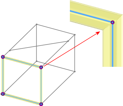
- Click in Groups and select each edge shown to create Group1.
The Settings section expands and the selected edges appear as Path segments.
-
Under Settings, select
Apply corner treatment and click
End Miter
 .
.
Use
Zoom
to Area

on the View toolbar to see the mitered corners.
The sample part in this lesson creates structural members along straight
segments only. However, you can also create structural members along curved
segments.