Creating Detail Views
A detail view shows a specified area from the drawing at an enlarged scale.
Use the AM_Detail command to generate a detail view from a specified area of a drawing.
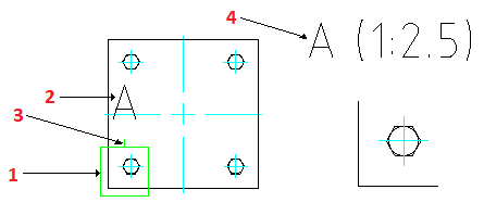
The command creates the following entities:
- Detail boundary
- Detail view identifier
- Annotation leader
- Detail view label
In the detail view, dimensions ignore the scale factor. To display the correct dimension values, use a dimensioning style according to the detail view scale.
When you move or resize the detail boundary using grip points, the corresponding detail view becomes invalid. To update the corresponding detail view, double-click its border.
If you delete a detail boundary, the corresponding detail view is not deleted. If you delete a detail view, the corresponding detail boundary and detail view label are also deleted.
To specify the area from the drawing use the following methods:
- Specify a circular boundary
- Specify a rectangular boundary
- Specify a Circle, an Ellipse, or a closed PolyLine
To create a detail view with a circular boundary:
- Do one of the following:
- On the ribbon, click Mechanical Content > Details > Detail View > Create.
- On the menu, click Mechanical Content > Details > Detail View > Create.
- Type AM_Detail.
- In the graphics area, specify the point to use as the center of the area to detail.
- Specify the radius of the circular area.
- In the Detail dialog box specify the properties of the detail view, such as:
- Scale
- Label
- Detail view location (Model space, Sheet, or both)
- Click OK.
The boundary appears attached to the cursor.
- In the graphics area, click to place the detail view.
To create a detail view with a rectangular boundary:
- Do one of the following:
- On the ribbon, click Mechanical Content > Details > Detail View > Create.
- On the menu, click Mechanical Content > Details > Detail View > Create.
- Type AM_Detail.
- Specify the Rectangle option and press Enter.
- In the graphics area, specify the first corner of the rectangular area.
- Specify the opposite corner of the rectangular area.
- In the Detail dialog box specify the properties of the detail view, such as:
- Scale
- Label
- Detail view location (Model space, Sheet, or both)
- Click OK.
The boundary appears attached to the cursor.
- In the graphics area, click to place the detail view.
To create a detail view using an existing closed contour:
- Do one of the following:
- On the ribbon, click Mechanical Content > Details > Detail View > Create.
- On the menu, click Mechanical Content > Details > Detail View > Create.
- Type AM_Detail.
- Specify the Entity option and press Enter.
- In the graphics area, specify a Circle, an Ellipse, or a closed PolyLine.
- In the Detail dialog box specify the properties of the detail view, such as:
- Scale
- Label
- Detail view location (Model space, Sheet, or both)
- Click OK.
The boundary appears attached to the cursor.
- In the graphics area, click to place the detail view.
Command: AM_Detail
Menu: Mechanical Content > Details > Detail View > Create
Ribbon: Mechanical Content > Details > Detail View > Create