Dimension Extension Lines
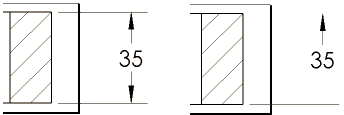
You can change the default attachment point of dimension
, slant the extension lines, flip the direction of a leader, and drag extension lines between the center, minimum, and maximum attachment points of arcs and circles.
You can specify in the
Dimension PropertyManager
that extension lines break when they cross other extension lines and specify in Tools, Options, Document Properties,
Dimensions
that the lines break only around dimension arrows.
You can hide and show dimension lines and extension lines. Right-click a dimension line or extension line and select Hide Dimension Line or Hide Extension Line. To show hidden lines, right-click the dimension or a visible line and select Show Dimension Lines or Show Extension Lines.

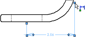
To change the attachment point or length of dimension extension lines:
-
Select a dimension.
Handles  are displayed at the attachment end of the extension lines. The pointer changes to
  when it is over a handle.

-
Drag a handle to the desired position or to a vertex.
If you choose a vertex, the default extension line gap is used. In sketches, the value of the dimension changes to reflect the new attachment point.
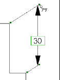
To slant dimension extension lines:
When you insert or select a dimension, handles  appear so you can drag the dimension to slant the extension lines. Drag a handle at the end of the extension line nearest the arrow (the pointer changes to
  when it is over a handle that effects the slant).
 To return the dimension to its original position, right-click the dimension and select Display Options, Remove Slant. You can also drag the handle until the dimension snaps back to its original position.

To flip the direction of a dimension leader:
If a vertical dimension is displayed with horizontal text (in ANSI standard, for example), you can flip the direction of the leader.
Select the dimension, then click the handle at the bend in the leader (the pointer changes to  when it is over the handle).
Related Topics
Jogging dimension extension lines