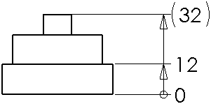
Ordinate Dimensions
Ordinate dimensions are a set of dimensions measured from a zero ordinate in a drawing or sketch. In drawings, they are reference dimensions
and you cannot change their values or use the values to drive the model.
Ordinate dimensions are measured from the axis you select first. The type of ordinate dimension (horizontal or vertical) is defined by the orientation of the points you select.
You can dimension to edges, vertices, and arcs (centers and minimum and maximum points). You can also dimension to midpoints when you add ordinate dimensions.
Ordinate dimensions are automatically grouped to maintain alignment. When you drag any member of the group, all the members move together. To disconnect a dimension from the alignment group, right-click the dimension, and select Break Alignment.
You can drag the zero dimension to a new position, and all the ordinate dimensions update to match the new zero position.
If adjacent dimensions are very close together, the leaders are automatically jogged as needed to prevent overlapping text. Drag handles are displayed at the bends when you select an ordinate dimension with a bent leader. You can remove the bend, or add a bend to a different ordinate dimension.
 You can set ordinate dimension document properties in Document Properties - Ordinate Dimensions. You can specify that the leaders not be automatically jogged by clearing Automatically jog ordinates.
To create ordinate dimensions:
-
Click Ordinate Dimension  on the Dimensions/Relations toolbar, or click Tools, Dimensions, Ordinate.
 You can select
Horizontal Ordinate Dimension
 or
Vertical Ordinate Dimension
 to specify the direction of the dimensions.
-
Click the first item (edge, vertex, and so on) from which all others will be measured to be the base (the 0.0 dimension), and click again to place the dimension outside the model.
-
Click the edges, or vertices, or arcs you want to dimension using the same ordinate. As you click each item, the dimension is placed in the view, aligned to the zero ordinate.
-
Select another mode or another tool or press Esc to exit from the ordinate mode.
To add more dimensions along the same ordinate:
-
Right-click an ordinate dimension, and select Add To Ordinate.
-
Click the edges, or vertices, or arcs you want to dimension using the same ordinate. As you click each item, the dimension is placed in the view, aligned to the zero ordinate.
-
Select another mode or another tool or press Esc to exit from the ordinate mode.
To modify ordinate dimensions:
You can modify ordinate dimensions using commands on the shortcut menu. Right-click an ordinate dimension, select Display Options, then choose from these options:
-
Align Ordinate. Aligns all the dimensions along the ordinate with the 0.0 ordinate.
-
Jog. Bends the leader line of a dimension and allows you to reposition the dimension.
-
Re-Jog Ordinate. Applies the automatic jogging algorithm to the ordinate dimensions.
-
Show Parentheses. Adds parentheses around the selected dimensions.

To display as chain dimensions:
-
Select an ordinate dimension.
-
Click the Leader tab and select Ordinate chain.
-
Click  .
.
 Select
Display as chain dimension in
Document Properties - Ordinate Dimensions
to chain all ordinate dimensions in the drawing.