Callouts are text-filled boxes that appear in the graphics area when you use certain tools. Handles allow you to dynamically click, move, and set certain parameters without leaving the graphics area.
Callouts
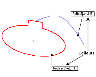
Callouts help you easily distinguish between different entities. For example, these callouts show the sweep profile and the sweep path. You can drag these callouts to reposition them, but you cannot use them to change any properties of the entity to which they refer.
Some callouts, such as those for chamfers, display figures that you can edit to manipulate the size of the entity.
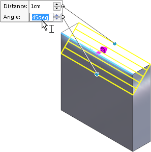
In this example, you can edit the callout in the graphics area.
When there are more than five visible callouts in the graphics area, a pushpin control appears with each callout to let you fix the position of the callout.
| Pushpin disabled |
 |
When you zoom, rotate, or move the model, the callout is repositioned. |
| Pushpin enabled |
 |
When you zoom, rotate, or move the model, the callout remains in the same location in the graphics area. Other callouts move with the model. |
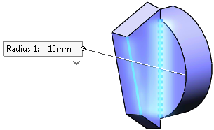
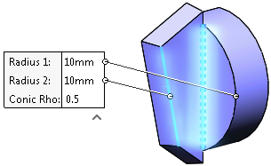
When a callout for a feature such as an asymmetric fillet contains multiple values, a control below the callout lets you expand it to see all values or collapse it to see the primary value:
 |
 |
| Callout collapsed |
Callout expanded |
Handles
The handle color is set in in the System colors box. Active handles are the Highlight color. Inactive handles are the Inactive Entities color.
Handles span the length of extrusions. Drag the handle to the desired extrude depth, and the handle spans that length.
You can also drag the pointer (instead of the handle) to the desired extrude depth. Click the handle, then drag the pointer in either direction. In the example below, the pink handle is active and the gray handle is inactive.
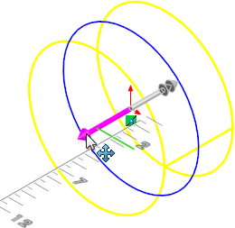
One handle has one arrow head, and the other handle has two arrow heads, to help you see which direction the handle applies to.