Main Area
The main area of the Technical Illustration workshop
lets you store settings using profiles, manage vectorization, options, BOM and callout visibility.
ProfileProfiles store your settings for future use. For details, see
About Profiles for Workshop Settings. Vectorization
| Command Name |
Description |
|---|
| Detail view |
Defines a portion of your scene to save as an image file or to capture as a Vector Image 2D panel.
- Select
Detail view.
The
Image area crop box appears in the viewport.
- Move or resize the image area as needed.
-
To limit the image to specific actors,
select one or more actors.
When no actors are selected, the image will contain everything within the image area.
-
Do one of the following:
-
To save the image area to a file, click
Save As
 . .
-
To create a Vector Image 2D panel, click
Create
 .
.
- To dismiss the image area, click
 (upper-right corner of the image area) or clear
Detail view. (upper-right corner of the image area) or clear
Detail view.
|
| Create |
(Available when
Detail view is selected.) Creates a detail view and adds it to the 3D scene as a Vector image 2D panel. |
| Preview |
(Available when
Detail view is cleared and no Vector image 2D panel is selected.) Generates an SVG preview image using your current workshop settings and displays it in your Web browser (when the
ExternalVectorViewWindow advanced property is selected - see Advanced Settings) or Composer. You can resize the Composer preview pane by dragging the viewport splitter bar.
Note:
ExternalVectorViewWindow is ignored on 64-bit operating systems. SVG previews are always displayed in Internet Explorer.
|
| Update |
(Available when
Detail view is cleared and a Vector Image 2D detail view is selected in the viewport.) Updates one or more detail views with changes in your 3D scene or different detail view options.
Note:
Detail views are not updated with changes in camera orientation and actor visibility.
|
| Save As |
Saves the active viewport pane (or a portion of it when
Detail view is selected) as a vector image using the current workshop settings. In the Save Vectorization As dialog box, choose from the following formats:
-
SVG (.svg) (Scalable Vector Graphics) - An XML format for describing two-dimensional vector graphics.
-
EPS (.eps) (Encapsulated PostScript) - A format commonly used to transfer images between applications.
Notes:
- When opening an EPS file in another application, users might need to substitute fonts referenced by the file with available PostScript fonts. - EPS files do not support transparency. Transparent features appear as opaque in EPS files.
- EPS files do not support unicode text.
-
SVGZ (.svgz) - SVG images saved with gzip compression.
-
CGM (.cgm) (Computer Graphics Metafile)- A file format defined by ISO/IEC 8632 for 2D vector graphics, raster graphics, and text.
|
| Lines |
Enables lines in vector output. Set options on the
Lines Tab tab.
Note:
Clearing
Lines,
Color regions, and
Shadows results in empty vector images.
|
| Color regions |
Retains colors in vector output. Set options on the
Color Regions Tab tab. |
| Shadows |
Generates shadow effects in vector output using ShadowCaster™ technology. Set options on the
Shadows Tab tab.
|
Options
| Tab Name |
Description |
|---|
| Lines
|
(Available when the
Lines check box is selected.) See
Lines Tab. |
| Color Regions |
(Available when the
Color regions check box is selected.) See
Color Regions Tab. |
| Shadows |
(Available when the
Shadows check box is selected.) See
Shadows Tab. |
| Hotspots |
See
Hotspots Tab.
|
| Options |
See
Options Tab. |
BOM and callout visibility
| Icon |
Command Name |
Description |
|---|
 |
Show or Hide BOM Table |
Toggles visibility of the BOM table in the viewport. |
 |
Show or Hide Callouts |
Toggles visibility of callouts in the viewport. |

Lines Tab
The Lines tab lets you specify what model lines to display (visible lines, hidden lines, outlines, silhouettes) and optimization methods such as hidden-line removal (HLR).
Note:
The
Lines vectorization option must be enabled.
| Command Name |
Description |
|---|
| Show visible lines |
Includes outlines and silhouette lines for visible actors in the vector output.
You can select
Same color for all actors and choose a line color, or clear this option to use actor colors.
You can configure visible line styles for rendering layers by enabling
Custom Render Mode and setting the
Visible lines style for Technical Illustration property. See Mode Commands. |
| Show hidden lines |
Includes outlines for actors hidden by other actors (internal actors) in the vector output.
You can select
Same color for all actors and choose a line color, or clear this option to use actor colors.
|
|
| Disabled |
Enabled |
Note:
In
Custom Render Mode, you can define a priority for the display of hidden lines. In this case, hidden lines are visible for rendering layers with higher priorities (even when
Show hidden lines is cleared).
Note that you can configure hidden line styles for rendering layers by setting the
Hidden lines style for Technical Illustration property.
|
| Show cutting lines |
Includes cutting lines (from cutting planes) in the vector output.
You can select
Same color for all actors and choose a color, or clear this option to use actor colors.
Notes:
This option does not affect hatch lines:
- Hatch lines, when displayed in the viewport, are always visible in vector output.
- Hatch-line color is determined by the cutting plane
property.
- To include capped/hatched surfaces in vector output,
HardwareSupport.Advanced (Application Preferences - Advanced Settings) must be enabled.
|
| Show collaboration |
Includes collaborative actors, such as arrows and labels, in the vector output. You can select
Same color for all actors and choose a color, or clear this option to use the actor colors.
|
|
| Disabled
|
Enabled
|
|
| Global line width |
Scales vectorized line weights by multiplying
Outline width,
Silhouette width, and collaborative actor line widths. For example, if
Global line width is 3 and
Silhouette width is 2, silhouette lines are 6 pt. |
|
Specifies what outline style to use in vector output. For details, see
Mode Commands . .
|
|
Sets the
width for outlines. Outline widths are calculated as follows:
Global line width x
Outline width For example, if
Global line width is 3 and outline
Width is 2, outlines are 6 pt. |
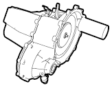
| Show silhouettes
|
Generates silhouette lines in addition to outlines.

|
|
| Disabled |
Enabled
(Model silhouette)
|
|
|
(Available when
Show silhouettes is selected.) Specifies how silhouette lines are generated:
-
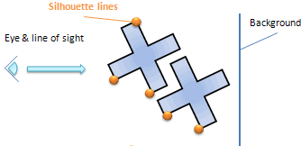
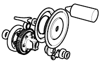
Crest - Generates silhouettes for actor perimeters and significant actor edges.
| Silhouette generation method |
|
| Example |
|
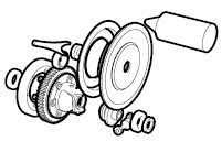
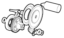
-
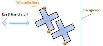
Per actor - Generates silhouettes for actor perimeters.
| Silhouette generation method |
|
| Example |
|
-
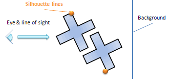
Model - Generates silhouettes for perimeters around contiguous actors (contiguous in the 2D vector output, not necessarily in the 3D scene).
| Silhouette generation method |
|
| Example |
|
|
|
(Available when
Show silhouettes is selected.) Sets the width for silhouette lines. Silhouette widths are calculated as follows:
Global line width x
Silhouette width For example, if
Global line width is 3 and silhouette
Width is 2, silhouette lines are 6 pt. |
| Shadow width |
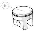
Generates gaps around overlapping actor outlines, which can improve image readability.
|
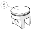
| Attach shadow width |
Generates gaps around attachment lines (such as callout lines), which can improve image readability.
|
|
| 1 pt
|
6 pts
|
|
| Refinement |
Sets the tolerance step between a vectorized line and the real 3D curve. A higher value improves the vectorized output but increases file size.
|
| Bezier generation |
Creates accurate bezier curves to smooth generated polylines. To create smaller vector files or to improve vectorization speed, clear this option.
|
| Ellipses generation (ortho mode only) |
(
Camera Perspective Mode must be disabled.) Detects 3D circles and ellipses and traces them as elliptic objects (no segments), which can reduce vector file sizes. To improve vectorization speed or if artifacts appear, clear this option.
|
| Back culling |
Disables rendering of back faces (faces not visible from the currentcamera angle). Back culling increases rendering speed, but some front faces might disappear when model faces are not well oriented.
|
| Occlusion culling |
Detects hidden actors and prevents them from being rendered. Occlusion culling can increase vectorization speed (depending on your video card), but very small parts (as compared to the rest of the geometry) might be omitted. If parts are missing from your technical illustration, try increasing the size of your viewport or disable occlusion culling.
|

Color Regions Tab
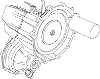
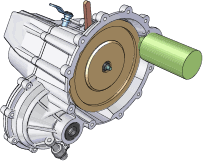
The Color Regions tab lets you include color in your vector output.
Note:
The
Color regions vectorization option must be enabled.
| No Color Regions |
Color Regions |
|---|
|
|
| Command Name |
Description |
|---|
| Light |
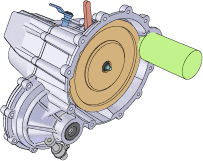
Enables the lighting effect, which creates color variations. When disabled, colors are flat. Clearing this option might produce more predictable color assignments in your vector output.
|

|
| Disabled |
Enabled |
|
| Compute regions per actor (time intensive)
|
Creates one group per actor, allowing more color variation. Each actor uses the same color palette. Color region calculation is performed using one process per actor instead of one process for the entire model, which can greatly increase processing time.
|
| Color depth |
Specifies the maximum number of colors, including black and white. Specify a value between 1 and 64. For example, specify 5 for black, white, and 3 additional colors.
Note:
Color palette calculation is complex and depends on a number of factors. For example, you might get very different results depending on whether
Light is selected.
|
| Level of detail |
Specifies the maximum tolerance between a curve and its approximated line. If this option is unavailable, ensure that
HardwareSupport.Advanced (Application Preferences - Advanced Settings) is selected. If the option is still unavailable, your video card likely does not support this feature. Note:
If you find that when using the maximum level of detail, the vector output is not precise enough, you can try to specify a value above 100 for the DetailLevel option, in category. See Advanced Settings.
|

Shadows Tab
The Shadows tab let you manage shadows and contour lines in vector output.
Notes:
-
The
Shadows vectorization option must be enabled.
- To use shadows with color regions, clear
Compute regions per actor.
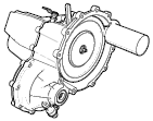
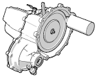
| No Shadows |
Shadows |
|---|
|
|
| Command Name |
Description |
|---|
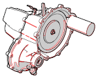
| Contour |
Generates shadow border lines of the specified color.
Note:
Contour lines are not visible when using color regions.

|
|
| Disabled
|
Enabled, Red
|
|
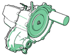
| Fill |
Generates shadows of the specified color.

|
|
| Black
|
Green
|
|
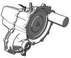
| Transparency |
(Available when
Fill is selected.) Specifies the shadow transparency (0 = opaque, 100 = transparent).

|
|
| 80%
|
40%
|
|

Hotspots Tab
The Hotspots tab lets you manage hotspots in vector output.
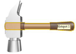
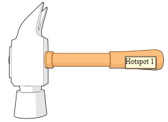
Hotspots are active areas in vector images created from Composer custom hotspots, event links, and BOM information. Notes:
- In vector outputs, hotspots are highlighted only on the visible section of parts, and not on hidden sections. Therefore, the visualization is different in Composer and in the vector output.
| Composer |
Vector Output |
|---|
|
|
- Only
file://,
http://, and
ftp:// links are valid in vector output. Composer-specific URLs (such as
view:// and
play://) are ignored.
- You can remove hotspot tooltips in SVG output using the
SvgOutput.ShowTooltip advanced application preference. See Advanced Settings.

Options Tab
The Options tab lets you manage output page format, CGM options, and Tech Illustrator options.
Page setup
| Command Name |
Description |
|---|
| Use document's paper |
Uses the document paper space to define the output page format. For details, see
Document Properties - Paper Space. When this option is cleared, the
Format and
Orientation options define the page. |
| Format |
(Available when
Use document's paper is cleared.) Specifies the page format:
-
Viewport ratio - Defined by
Height and the viewport width-to-height ratio.
-
Custom - Defined by
Width and
Height.
-
Standard formats - Standard formats such as
Letter and
A4.
|
| Orientation |
(Available when
Use document's paper is cleared.) Specifies the paper orientation:
|
Advanced
| Command Name |
Description |
|---|
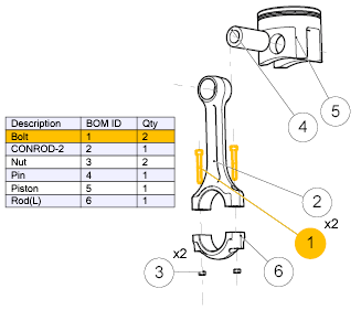
| Make groups (required for BOM table) |
Creates groups, which are containers for related elements. You must enable this option to include BOM tables in your vector output.
|
| High quality capping |
Improves vectorization results of cutting-plane capping in complex models with small holes. For most models, clear this option to improve vectorization performance.
|
CGM optionsComputer Graphics Metafile (CGM) is an ISO standard for vector and composite vector/raster images.
| Command Name |
Description |
|---|
| Profile |
Specifies the CGM format to generate:
-
WebCGM- Web interoperability specification created by the W3C and CGM Open Consortium.
-
S1000D (2.x) - International specification for the procurement and production of technical publications, version 2.x.
-
ATA2200 - Air Transport Association (ATA) iSpec 2200 specification for aircraft maintenance.
-
S1000D (4.x) - International specification for the procurement and production of technical publications, version 4.x.
Notes:
- CGM supports limited fonts. Visit the following website for additional information:
http://www.w3.org/TR/NOTE-cgm-970618
- In the case of S1000D (4.x), if you choose to generate a companion file, you can customize hotspot properties to be compliant with S1000D 4.x in the CGM output and in the XML companion file. See Hotspot Properties for custom hotspots created from the Assembly pane or from the Collaboration pane, and see Meta-Properties for hotspots generated from BOM IDs.
|
| Metafile name |
Specifies the metafile name. |
| Generate companion file |
Generates an XML file in addition to the CGM file. |

Multiple Tab
The Multiple tab lets you generate multiple vector images from your animation, views, or both.
| Command Name
|
Description
|
| Animation
|
Creates multiple images from an animation. Specify the image
frequency as one of the following:
- Frames between two images
- Images per second
Image files are named
<filename>_anim
<n><type>< ,
where:
-
<filename> is the file name you
specify in the
Save As dialog box (when you click
Save As).
-
<n> is the image index based on the
frequency and range you specify. For example, when you specify 30 images per
second starting at 5 seconds, the image indexes are 150, 151, and so on.
-
<type> is the format extension, as
determined by
Save as type in the
Save As dialog box.
|
| Range
|
(Available when
Animation is selected.) Specifies the
animation segment to capture:
-
All - The entire animation
-
Selection - The selected timeline segment

-
Seconds - The specified range in seconds
|
| Markers
|
Creates one image per marker in the timeline.
|
| Milestones
|
Creates one image per milestone in the timeline.
|
| Views
|
Creates images for all views (see
Views pane). To create images for the current view
only, clear this option.
|
| 360° Capture
|
Captures a defined number of images of the model
along a vertical axis performing a 360° clockwise rotation. The vertical axis
determines the orientation of the camera.
The vertical axis used in the one defined in the viewport
properties (see
Viewport Properties).
- If Z is defined as the vertical axis, then the rotation plane
will be XY.
- If Y is defined as the vertical axis, then the rotation plane
will be XZ.
- If X is defined as the vertical axis, then the rotation plane
will be YZ.
Enter the number of images you want to capture along the 360° path
in the
Number of Images box.
|
| File-name template
|
(Available when
Markers,
Milestones,
Views, or
360° Capture is selected.) Specifies the
naming convention for image files. You can specify valid file-name characters
and the following case-sensitive keywords:
| %filename%
|
The file name specified by
File name in the
Save As dialog box.
|
| %viewname%
|
The view name, as listed in the Views pane.
Note:
Not applicable to
360° Capture.
|
| %markername%
|
The marker name, as listed in the
timeline and in the Markers pane.
Note:
Not applicable to
360° Capture.
|
| %index%
|
A counter from 1 to the number of
views. Index values have the same number of characters (1-9, 01-99, 001-999)
for all files created.
|
Notes:
- The
Save As dialog box does not consider
File-name template when checking for
existing files. Use caution to avoid overwriting files unintentionally.
- Do not specify file-name extensions in
File-name template. Extensions are
determined by
Save as type in the
Save As dialog box.
- When
File-name template does not contain
%filename%,
File name in the
Save As dialog box is still required but
is not used in the file names.
- When
File-name template is blank:
- files generated from markers are named
%filename%_%markername%.
- files generated from milestones are named
%filename%_view.
- files generated from views are named
%filename%_%viewname%.
|
|