You can use the interaction viewer to visualize the behavior of multibody
parts and assemblies during simulations.
Results
 |
Show
Geometry Based Interactions
|
Switches the visibility of the
geometry-based interactions. When activated, renders the touching
geometric entities (edges, faces, or bodies) between the components
participating in an interaction definition (global or local). All detected interaction pairs are listed
accordingly under Manual
Interaction or Global
Interaction.
- Click an interaction definition in the list
to view the color rendering of the area of interaction. The
components associated with the interaction definition are
listed under each node.
- Right-click an interaction node, and select
Zoom to
Selection.
- You can render one interaction pair at a
time, or click Show all
interactions to render all interaction pairs
simultaneously.
The geometry-based
interactions include these areas of the components with
touching geometric entities. To view an interaction
pair between faces that are not initially touching,
select Include solver
generated interactions (mesh
required).
|
 |
Show
Solver Based Interactions
|
Switches the visibility of the
solver-based interactions. When activated, renders the areas of
interaction at the mesh element level detected by the solver before
starting the analysis. |
| |
| |
Show
unselected bodies |
Active if you select components
and not the whole assembly in Select
Components. |
 |
 |
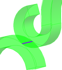
| Plot of a
geometry-based contact. Rendering of the touching edge between the
two components. |
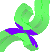
Plot of a solver-based contact
set. Rendering of mesh elements that participate in contact
formulation. |