Now you plot the factor of safety for different components of the
assembly. Then, you examine the steps to improve it.
-
Right-click Results
 and select Define Factor Of Safety Plot
 .
.
-
In the PropertyManager, under Step 1 of
3, select All and for Criterion
 select Automatic.
Setting the Criterion to Automatic imposes the default failure criterion assigned in the
Material dialog box for each material. For
beams, columns, and roof, the default failure criterion is set to Max
von Mises Stress whereas for the vertical glass panels, the default failure
criterion is set to Mohr Coulomb Stress.
For more information about the different failure criteria, see SOLIDWORKS Simulation Help: Failure
Criteria.
-
Click
 .
.
-
Under Step 2 of 3, set
Multiplication factor to 1 and click
 .
.
-
Under Step 3 of 3, select
Areas below factor of safety, set Minimum factor of safety to 1 and click
 .
.
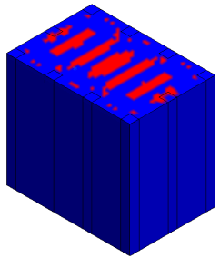
The roof is the only unsafe region with a
factor of safety < 1 as highlighted in red.

-
Rotate the model in the graphics window and verify that all the other
components are safe.