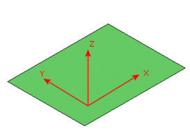
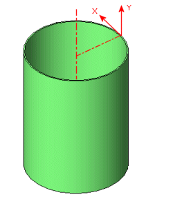
For a planar shell, select a plane that is parallel to the shell as the reference geometry for orthotropic material properties. For a cylindrical shell, select the axis of the cylinder as the reference geometry.
 |
 |
| The reference plane is parallel to the shell plane. The X and Y directions of an orthotropic material lie in the plane and the Z-axis is normal to the plane. |
For a cylindrical shell, select the axis of the cylinder as the reference geometry. The Y-axis is parallel to the axis of the cylinder and the X-axis is tangential.
|
For composite shells, the X, Y and Z directions for orthotropic material definition are defined differently for each ply depending on the ply angle. Reference geometry is not considered for orthotropic material definition.
In general, the software modifies the reference geometry as follows:
- The software transforms the coordinate system defined by the reference geometry such that the Z-axis becomes normal to the plane of the shell. The plane of the shell is defined by the three corner nodes.
- If the angle between the X-axis of the selected reference geometry and the normal to the shell plane is larger than 45o, the program projects the X-axis of the reference geometry on the shell plane to define the modified X-axis.
- If the angle between the X-axis of the selected reference geometry and the normal to the shell plane is less than 45o, the program projects the Y-axis of the reference geometry on the shell plane to define the modified X-axis.
- The Y-axis of the modified reference geometry is then defined to complete a right-hand Cartesian coordinate system.