Next, you display the BOM, cut list, connector tables, and balloons in
the drawing.
-
In the Flatten Route
PropertyManager, for Flatten Type, select
Annotation.
-
For Flatten Options,
select Display 3D connectors.
-
Select Drawing Options
and select the following:
- Electrical BOM
- Cut
List
- Connector
Table
- Display
Connector Balloons
- Display Wire
Balloons
Click
Yes if prompted to continue
before selecting drawing options.
-
Click
 .
.
-
Click Yes when prompted
to add a length field to the BOM template.
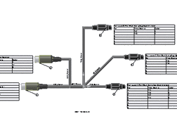
The drawing includes the flattened harness, the BOM, the cut
list, the connector tables, and the balloons.

The flattened configuration and drawing are simplified
representations of the route. The annotations on the route segments display
the length of the routed wire.
-
Click .
-
In the Save As dialog box,
navigate to a directory away from your installation directory and save the
drawing (along with its references) as my_top_assy_fromto_drawing.SLDDRW. Close the drawing.
-
Click and save the assembly in your local directory as my_top_assy_fromto_completed.SLDASM.
-
Close
the assembly. Then in the top bar, in your profile, click Work Offline to reconnect to the 3DEXPERIENCE platform.
Congratulations! You have completed this tutorial.