Datum Feature Symbols
You can attach a datum feature symbol to the following items:
In a part or assembly, on a planar model surface
or on a reference plane
In a drawing view, on a surface that appears as
an edge (including silhouette edges) or on a section view surface to identify
datum planes in the part
A geometric tolerance symbol frame
In a note
On a dimension,
except for:
You can
also drag and drop datum feature symbols onto existing dimensions and
geometric tolerance frames.
|

|

|

|
|
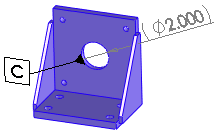
Datum feature symbol attached to model surface |
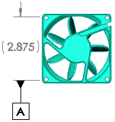
Datum feature symbol attached to dimension |
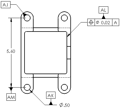
Datum feature symbols attached to model surface, dimensions,
and geometric tolerance symbol frame |
To insert datum feature symbols:
Do one of the following:
For parts, click Datum  (DimXpert
toolbar) or Tools, DimXpert,
Datum. See DimXpert for Parts Overview.
For drawings, click Datum
Feature  (Annotation toolbar) or Insert, Annotations,
Datum Feature Symbol.
 You can pre-select a dimension
or geometric tolerance symbol to attach the datum feature symbol to the
annotation, or you can drag the datum feature symbol onto the dimension
or geometric tolerance symbol after it is created.
Edit the options in the Datum Feature PropertyManager.
Click in the graphics area to place the attachment
and then the symbol. The attachment (such as a filled triangle) bends
with the angle of the drawing edge.
Continue inserting as many symbols as needed.
Click OK  .
.

If you drag a datum feature symbol off the model edge, an extension
line is added.
To edit a datum feature symbol, select the symbol.
NOTE: If you use ANSI dimensioning
standards, you can display datum feature symbols in the 1982 style. To
select this option for the active document, click Tools, Options,
Document Properties, Annotations,
Datums.
Select Display datums per 1982:

Related Topics
DimXpert
Auto Dimension Scheme PropertyManager