Creep Models
Creep is a time dependent strain produced under a state of constant stress. Creep is observed in most engineering materials especially metals at elevated temperatures, high polymer plastics, concrete, and solid propellant in rocket motors. Since creep effects take long time to develop, they are usually neglected in dynamic analysis.
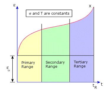
Creep curve is a graph between strain versus time. Three different regimes can be distinguished in a creep curve; primary, secondary, and tertiary (see the following figure). Usually primary and secondary regimes are of interest.

Two creep laws based on an “Equation of State” approach are implemented. Each law defines an expression for the uniaxial creep strain in terms of the uniaxial stress and time.
Classical Power Law for Creep (Bailey-Norton law)

where:
T = Temperature (Kelvin) (= input temperature + reference temperature + offset temperature)
C
T = A material constant defining the creep temperature-dependency
C0 is the Creep Constant 1 you enter in the Properties tab of the Material dialog box.
The units of the Creep Constant 1 must be entered in the SI unit system. The conversion factor is equal to 1/ (stress ^ (C1) * time^(C2)). The stress units are in N/m2 and time is in seconds.
C1 is the Creep constant 2, and C2 is the Creep constant 3 in the material properties dialog box.
The classical power law for creep represents primary and secondary creep regimes in one formula. Tertiary creep regime is not considered. “t” is the current real (not pseudo) time and sigma is the total uniaxial stress at time t.
To extend these laws to multiaxial creep behavior, the following assumptions are made:
For a numerical creep analysis, where cyclic loading may be applied, based on the strain hardening rule, the current creep strain rates are expressed as a function of the current stress and the total creep strain:

where:
