Expand IntroductionIntroduction
Expand AdministrationAdministration
Expand User InterfaceUser Interface
Expand SolidWorks FundamentalsSolidWorks Fundamentals
Expand Moving from 2D to 3DMoving from 2D to 3D
Expand AssembliesAssemblies
Expand CircuitWorksCircuitWorks
Expand ConfigurationsConfigurations
Expand SolidWorks CostingSolidWorks Costing
Expand Design CheckerDesign Checker
Expand Design Studies in SolidWorksDesign Studies in SolidWorks
Expand Drawings and DetailingDrawings and Detailing
Expand DFMXpressDFMXpress
Expand DriveWorksXpressDriveWorksXpress
Expand FloXpressFloXpress
Expand Import and ExportImport and Export
Expand Large Scale DesignLarge Scale Design
Expand Model DisplayModel Display
Expand Mold DesignMold Design
Expand Motion StudiesMotion Studies
Expand Parts and FeaturesParts and Features
Expand RoutingRouting
Expand Sheet MetalSheet Metal
Collapse SimulationSimulation
Welcome to SolidWorks Simulation Online Help
Access to Help
Conventions
Legal Notices
Expand Analysis BackgroundAnalysis Background
Expand Simulation FundamentalsSimulation Fundamentals
Expand Simulation OptionsSimulation Options
Expand Simulation StudiesSimulation Studies
Expand Design StudiesDesign Studies
Expand 2D Simplification Study2D Simplification Study
Expand Composite ShellsComposite Shells
Expand Loads and RestraintsLoads and Restraints
Expand MeshingMeshing
Collapse Material PropertiesMaterial Properties
Assigning Materials
Applying a Material
Removing a Material
Expand Creating a Custom MaterialCreating a Custom Material
Creating a Material Library
Managing Favorite Materials
Using Drag and Drop to Define Materials
Material Properties Used in SolidWorks Simulation
Isotropic and Orthotropic Materials
Temperature - Dependent Material Properties
Defining Stress-Strain Curves
Expand Material Dialog BoxMaterial Dialog Box
Collapse Material ModelsMaterial Models
Material Models
Plasticity Drucker - Prager Model
Plasticity Tresca Model
Plasticity von Mises Model
Viscoelastic Model
Linear Elastic Orthotropic Model
Linear Elastic Isotropic Model
Hyperelastic Ogden Model
Hyperelastic Mooney - Rivlin Model
Nitinol Material Model
Nonlinear Elastic Model
Creep Models
Comparison of Tresca and von Mises Criteria for Plasticity
Generalized Maxwell Model
Hyperelastic Blatz - Ko Model
Expand ParametersParameters
Expand Analysis LibraryAnalysis Library
Expand Viewing ResultsViewing Results
Expand Study ReportsStudy Reports
Expand Checking Stress ResultsChecking Stress Results
Expand SimulationXpressSimulationXpress
Expand SketchingSketching
Expand Sustainability ProductsSustainability Products
Expand SolidWorks UtilitiesSolidWorks Utilities
Expand TolerancingTolerancing
Expand ToolboxToolbox
Expand WeldmentsWeldments
Expand Workgroup PDMWorkgroup PDM
Expand TroubleshootingTroubleshooting
Expand GlossaryGlossary
Hide Table of Contents

Linear Elastic Isotropic Model

A material is said to be isotropic if its properties do not vary with direction. Isotropic materials therefore have identical elastic modulus, Poisson's ratio, coefficient of thermal expansion, thermal conductivity, etc. in all directions. The term isothermal is some times used to denote materials with no preferred directions for coefficients of thermal expansion.

In order to define the isotropic elastic properties, you must define the elastic modulus E x .  The program assumes a value of 0.0 for Poisson's ratio n xy,if  no specific value is specified.  A common value for the Poisson's ratio is 0.3. The shear modulus G xy. is calculated internally by the program even if it is explicitly specified.

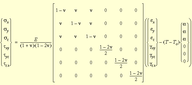
The stiffness matrix for an isotropic material contains only two independent coefficients. The following sections describe the isotropic stress-strain relations in two- and three-dimensions including the effect of thermal strains.

Isotropic Stress-Strain Relations

The most general form of the isotropic stress-strain relations including thermal effects is shown below:
Assumptions of Linear Elastic Material Models

Linear elastic material models make the following assumptions:

  • Linearity Assumption. The induced response is directly proportional to the applied loads. For example, if you double the magnitude of loads, the model's response (displacements, strains, and stresses) will double. You can make the linearity assumption if the following conditions are satisfied:

  • The highest stress is in the linear range of the stress-strain curve characterized by a straight line starting from the origin. As the stress increases, materials demonstrate nonlinear behavior above a certain stress level. This assumption asserts that the stress should be below this level. Some materials, like rubber, demonstrate a nonlinear stress-strain relationship even for low stresses.

  • The maximum displacement is considerably smaller than the characteristic dimension of the model. For example, the maximum displacement of a plate must be considerably smaller than its thickness and the maximum displacement of a beam must be considerably smaller than the smallest dimension of its cross-section.

  • Elasticity Assumption. The loads do not cause any permanent deformation. In other words, the model is assumed to be perfectly elastic. A perfectly elastic model returns to its original shape when the loads are removed.

Isotropic vs. orthotropic materials


Provide feedback on this topic

SOLIDWORKS welcomes your feedback concerning the presentation, accuracy, and thoroughness of the documentation. Use the form below to send your comments and suggestions about this topic directly to our documentation team. The documentation team cannot answer technical support questions. Click here for information about technical support.

* Required

 
*Email:  
Subject:   Feedback on Help Topics
Page:   Linear Elastic Isotropic Model
*Comment:  
*   I acknowledge I have read and I hereby accept the privacy policy under which my Personal Data will be used by Dassault Systèmes

Print Topic

Select the scope of content to print:


x

We have detected you are using a browser version older than Internet Explorer 7. For optimized display, we suggest upgrading your browser to Internet Explorer 7 or newer.

 Never show this message again
x

Web Help Content Version: SOLIDWORKS 2012 SP05

To disable Web help from within SOLIDWORKS and use local help instead, click Help > Use SOLIDWORKS Web Help.

To report problems encountered with the Web help interface and search, contact your local support representative. To provide feedback on individual help topics, use the “Feedback on this topic” link on the individual topic page.