Expand IntroductionIntroduction
Expand AdministrationAdministration
Expand User InterfaceUser Interface
Expand SolidWorks FundamentalsSolidWorks Fundamentals
Expand Moving from 2D to 3DMoving from 2D to 3D
Expand AssembliesAssemblies
Expand CircuitWorksCircuitWorks
Expand ConfigurationsConfigurations
Expand SolidWorks CostingSolidWorks Costing
Expand Design CheckerDesign Checker
Expand Design Studies in SolidWorksDesign Studies in SolidWorks
Expand Detailing and DrawingsDetailing and Drawings
Expand DFMXpressDFMXpress
Expand DriveWorksXpressDriveWorksXpress
Expand FloXpressFloXpress
Expand Import and ExportImport and Export
Expand Model DisplayModel Display
Expand Mold DesignMold Design
Expand Motion StudiesMotion Studies
Expand Parts and FeaturesParts and Features
Expand RoutingRouting
Expand Sheet MetalSheet Metal
Collapse SimulationSimulation
Expand SimulationXpressSimulationXpress
Expand SketchingSketching
Expand Sustainability ProductsSustainability Products
Expand SolidWorks UtilitiesSolidWorks Utilities
Expand TolerancingTolerancing
Expand TolAnalystTolAnalyst
Expand ToolboxToolbox
Expand WeldmentsWeldments
Expand Workgroup PDMWorkgroup PDM
Expand TroubleshootingTroubleshooting
Glossary
Hide Table of Contents

Creating Valid Sections for Circular Symmetry

The circular symmetry constraint is appropriate for simulations of models where the geometry, restraints, and loading conditions are repeated in a cyclical pattern with reference to a central axis.

To set up your model for applying circular symmetry restraints, you create a cut (or an assembly cut feature) to produce a section of the model that can be repeated in a cyclical pattern about a central axis of revolution. A valid cut section produces a complete part, when it is repeated with an equal spacing circular pattern feature, and there are no gaps or interferences between the sections. You cannot apply a circular symmetry restraint to an invalid section.

Example: Seven-blade impeller

You cut the model to produce an appropriate section that is one seventh of the original model.
impeller.png impeller_sketch.png

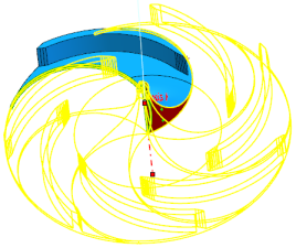
As the geometry, restraints, and loads are repeated cyclically about the central axis of the impeller, the circular symmetry restraint is appropriate for a simulation performed on a representative cut section of the impeller.

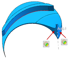
The sketch of the extruded cut has two equal radius arcs intersecting the center axis and the outer edge of the model. The position of the two arcs relative to the model and the arc radius are adjusted so that the cut fully encompasses a section of the model equal to one seventh of the original model. The angle between points on each arc located at the same distance from the center axis is 51.43 degrees, which is evenly divisible into 360 degrees (360 / 7).

impeller_cut_section.png impeller_circular_symmetry.png
Extruding the sketch creates a cut section that is valid for circular symmetry. Apply circular symmetry restraints to the cut faces. Applying circular symmetry restraints to a valid section creates a rendering of the whole model.


Provide feedback on this topic

SOLIDWORKS welcomes your feedback concerning the presentation, accuracy, and thoroughness of the documentation. Use the form below to send your comments and suggestions about this topic directly to our documentation team. The documentation team cannot answer technical support questions. Click here for information about technical support.

* Required

 
*Email:  
Subject:   Feedback on Help Topics
Page:   Creating Valid Sections for Circular Symmetry
*Comment:  
*   I acknowledge I have read and I hereby accept the privacy policy under which my Personal Data will be used by Dassault Systèmes

Print Topic

Select the scope of content to print:

x

We have detected you are using a browser version older than Internet Explorer 7. For optimized display, we suggest upgrading your browser to Internet Explorer 7 or newer.

 Never show this message again
x

Web Help Content Version: SOLIDWORKS 2014 SP05

To disable Web help from within SOLIDWORKS and use local help instead, click Help > Use SOLIDWORKS Web Help.

To report problems encountered with the Web help interface and search, contact your local support representative. To provide feedback on individual help topics, use the “Feedback on this topic” link on the individual topic page.