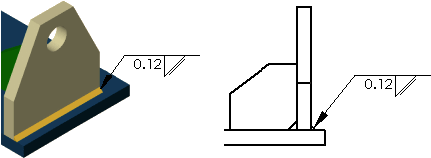
Weld Symbols
You can use the Weld
Symbol tool to add weld symbols to assemblies, drawings, vertices,
and edges or faces of parts. The software supports ANSI, ISO, GOST, and
JIS weld symbol libraries.
A weld symbol representing the
parameters you specify is created automatically when
you:
If you added weld symbols in
the model, you can import the symbols into the drawing by inserting
model items.

You can also construct weld symbols independently in a part, assembly,
or drawing document. When creating or editing a weld symbol, you can:
Add secondary weld fillet information to the weld
symbol for certain types of weld (Square
or Bevel, for example).
Choose a Leader
anchor of None.
Choose the text font for each weld symbol.
To insert a weld symbol:
-
Click Weld Symbol  (Annotation toolbar) or Insert,
Annotations, Weld
Symbol.
The Weld
Symbol Properties dialog box appears for ISO, BSI, DIN, JIS,
and GB standards. Different dialog boxes appear for ANSI
and GOST
standards.
Type in values and select symbols and options.
A preview
is displayed.
Click a
face or edge where you want to indicate a welded joint. If the weld symbol
has a leader, click to place the leader first, then click to place the
symbol.
 If you selected a face or
edge before you clicked Weld Symbol
 , the leader is already placed; click once to place the
symbol.
Click as
many times as necessary to place multiple weld symbols.
Click OK.
To edit a weld symbol: